ARDF DF3090
ACCESSORY CHECK
Check the quantity and condition of the accessories against the following list.
No. Description Q’ty 1 ARDF 1 2 Screw 2 3 Knob Screw 2 4 Stud Screw (Small) 1 5 Stud Screw (Large) 1 6 Attention Decal – Top Cover 1

INSTALLATION PROCEDURE

- Unplug the copier power cord before starting the following procedure.
- All tapes and shipping retainers.
Installation
- Insert the two stud screws ([A] is the larger stud, is the smaller stud).

[*]Mount the ARDF [A] by aligning the screw keyholes of the ARDF support plate over the stud screws.
[*]Slide the ARDF toward the front of the machine.
[*]Secure the ARDF with the two knob screws [C].

[*]Align the rear left corner of the platen sheet [A] with the corner on the exposure glass.
[*]Close the ARDF.
[*]Open the ARDF and check that the platen sheet is correctly attached.

[*]Lift the ARDF original tray.
[*]Slide the stamp holder [A] out and install the stamp cartridge in it, if necessary.


- After the stamp installation, be sure to slide the holder in correctly. If not, jam detection (J001) will occur.
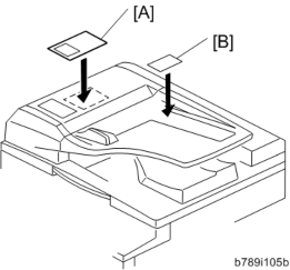
Installation
[*]Scanner rear cover [A]×3)

[*]Connect the harness [A].
Attach the bracket [A] ( ×1)
[*]
Fasten the grounding wire [A] ( ×1)
[*]

[*]Attach the rear cover.
[*]Plug in and turn on the main power switch of the machine, and then check the ARDF operation.
[*]Make a full size copy. Check that the registrations (side-to-side and leading edge) and image skew are correct. If they are not, adjust the registrations and image skew (see ARDF Image Adjustment in the "Replacements and Adjustments" chapter).
When feeding thin paper
When feeding thin paper, adjust the sliding tray to the point shown below [A]. When feeding normal paper, adjust the sliding tray to the point shown below . If not, it may cause problems as follows:
- Original jam
- Original curl
- Originals cannot be stacked neatly

- All tapes and shipping retainers.
- Unplug the copier power cord before starting the following procedure.
[*]SPDF DF3080
Installation
ACCESSORY CHECK
No. Description Q’ty Remarks 1 TAPPING SCREW:3×6 10 2 CLAMP:LWS-0711A 2 3 FERRITE CORE:K3 NF-70-A(N)BK0 1 4 FERRITE CORE:K3 NF-75(N)BK0 1 5 SCREW:HINGE:INNER BACK 2 6 BCU:TYPE-H1:ME-C1E:ASS'Y 1 7 PCB:IMAGE PROCESSING UNIT:TYPE-S1MD-SUB 1 8 BRACKET:1PASS:ADF 1 9 BRACKET:IPU_SUB 1 10 FULL DUG POINT SCREW:FIX:HINGE 2 11 DECAL:SET:ORIGINAL TABLE 1 12 DECAL::ORIGINAL OM
1

INSTALLATION PROCEDURE

- When you install this option, turn off the power supply to the machine, and unplug the power plug from the wall socket.
- If it is installed when the power is ON, it will result in an electric shock or a malfunction.

- Do not turn the power on until you perform “adjustment after installation,” otherwise it may not start normally.
Attaching the SPDF
- Place the unit on the machine temporarily, and remove the orange tape and shipping retainers.

- Remove the items in the package (boards, fixing screws, etc.).
- Attach the 2 stepped screws [A] to the machine.

Installation
- Align the hinges of the SPDF with the stepped screws, and attach them by sliding them in.

- Fix the SPDF to the machine (coin screws×2)

- Release the lever [A], open the pressure plate sheet , gently remove the protective sheet [C], and shut the pressure plate sheet.

[*]Remove the filament tape [D].
[*]Remove the platen sheet [A], and set it on the exposure glass. Align it with the left scale and rear scale of the printer.

Installation
[*]Close the SPDF slowly, and attach the platen sheet and SPDF.

Attaching the Sub IPU / Replacing the BCU
1. Controller cover [A]

1. Rear cover [A]

Scanner rear cover [A] ( ×3)
2.
Scanner rear small cover [A] ( ×2)
3.
Bracket [A] ( ×2)
4.
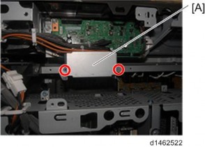
5. Attach the 2 clamps to the bracket provided.
Attach the bracket [A] to the frame ( ×2)
Installation
6.

- Retaining bracket [A]
×1)


- Pull out the connector [A] of the scanner cable.
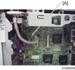
- Attach the provided ferrite core [A] to the scanner cable.
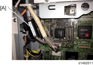
- Attach the provided bracket [A] to the IPU board
×1)

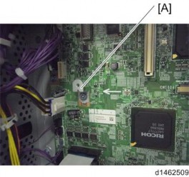
- Attach the IPU sub board [A], and insert the connector of the scanner cable
×3)

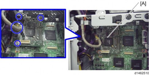
Installation
- Replace the BCU board [A]
×2,
 ×4)
×4)

- Since a tab is attached to the FFC, when removing, do not use force.
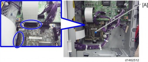
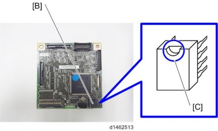
Remove the EEPROM from the original BCU board with a knob screwdriver or tweezers, and replace with the BCU board in the accessories.

[*]Remove it with the knob screwdriver or tweezers so as not to bend the terminals of the EEPROM.

[*]Attach the EEPROM with the correct orientation so that the depression [C] is up.
[*]Attach the bracket [A] of the CIS image cable to the frame, insert the connector in the SIO, and attach an earth wire [C]×2)
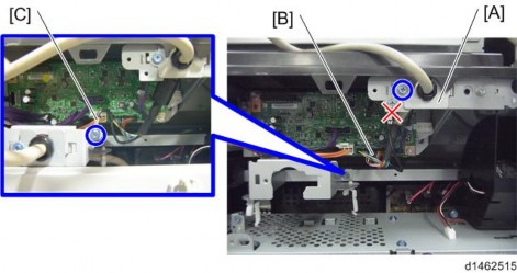
[*]Attach the bracket [A] of the I/F cable to the bracket attached in Step 16×1)
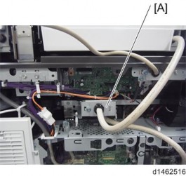
[*]Attach the ferrite core [A] provided to the I/F cable.
- Since a tab is attached to the FFC, when removing, do not use force.
