4.12.16 FUSING SHIELD DRIVE MOTOR 4-111
4.17.3 IPU 4-145
4.17.4 BCU 4-147
Replacing the NVRAM (EEPROM) on the BCU 4-147
4.17.5 CONTROLLER BOARD 4-148
NVRAMs on the controller board 4-149
4.17.6 HDD 4-150
Adjustment after replacement 4-151
4.17.9 HVP_TTS 4-152
4.18.9 MAIN EXHAUST FAN (D148/D149/D150) 4-162
4.19.1 SCANNING 4-167
D146/D147/D148/D149/D150 xii SM
Scanner sub-scan magnification 4-167
Scanner leading edge and side-to-side registration 4-167
4.19.2 ARDF 4-168
ARDF side-to-side, leading edge registration and trailing edge 4-168
ARDF sub-scan magnification 4-169
Copy Mode 4-172
Printer Mode 4-176
D146/D147/D148/D149/D150 xiv SM
This manual uses several symbols and abbreviations. The meaning of those symbols and abbreviations are as follows:
PostScript® is a registered trademark of Adobe Systems, Incorporated.
PCL® is a registered trademark of Hewlett-Packard Company. Ethernet® is a registered trademark of Xerox Corporation.
PowerPC® is a registered trademark of International Business Machines Corporation.
Other product names used herein are for identification purposes only and may be trademarks of their respective companies. We disclaim any and all rights involved with those marks.
Product Overview
Product Information
SM 1-1 D146/D147/D148/D149/D150
Product Overview
Scanner Unit
*1 Option
D146/D147/D148/D149/D150 1-2 SM
Product Overview
Product Information
Laser Exposure Unit
SM 1-3 D146/D147/D148/D149/D150
Product Overview
Image Transfer Unit
D146/D147/D148/D149/D150 1-4 SM
Product Overview
Product Information
PCDU
SM 1-5 D146/D147/D148/D149/D150
- PAPER EXIT 4-112
- PAPER EXIT UNIT 4-112
- PAPER EXIT SWITCHING SOLENOID 4-112
- PAPER EXIT SENSOR 4-113
- REVERSE SENSOR 4-114
- PAPER EXIT FULL SENSOR 4-115
- REVERSE MOTOR 4-115
- FUSING EXIT SENSOR 4-116
- PAPER FEED 4-117
- PAPER FEED UNIT 4-117
1st Paper Feed Unit 4-117
2nd Paper Feed Unit 4-118 - PAPER DUST COLLECTION UNIT 4-120
- PICK-UP ROLLER, PAPER FEED ROLLER, SEPARATION ROLLER, TORQUE LIMITER 4-120
- PAPER FEED SOLENOID 4-122
- PAPER FEED SENSOR 4-123
- VERTICAL TRANSPORT SENSOR 4-124
- LIMIT SENSOR 4-125
- PAPER END SENSOR 4-125
- REGISTRATION SENSOR 4-126
- PAPER FEED UNIT 4-117
- BY-PASS TRAY UNIT 4-127
- BY-PASS TRAY 4-127
- BY-PASS PAPER END SENSOR 4-129
- BY-PASS PICK-UP ROLLER 4-130
- BY-PASS PAPER FEED ROLLER 4-130
- BY-PASS SEPARATION ROLLER 4-131
- TORQUE LIMITER 4-131
- BY-PASS TRAY SIDE FENCE (D150 ONLY) 4-132
- DUPLEX UNIT 4-134
- DUPLEX UNIT 4-134
- DUPLEX/BY-PASS MOTOR 4-136
- DUPLEX ENTRANCE SENSOR 4-137
- DUPLEX JAM PROCESSING LED 4-139
- DUPLEX EXIT SENSOR 4-139
- DOUBLE FEED SENSOR (D150 ONLY) 4-140
- ELECTRICAL COMPONENTS 4-142
- OVERVIEW 4-142
SM xi D146/D147/D148/D149/D150
Printed Circuits/Parts Inside the Controller Box 4-142
Printed Circuits Behind the Controller Box 4-143
Printed Circuit/Parts Inside the Power Box 4-143
Printed Circuits Behind the Power Box 4-144 - IPU SUB (SPDF ONLY) 4-144
- OVERVIEW 4-142
4.17.4 BCU 4-147
Replacing the NVRAM (EEPROM) on the BCU 4-147
4.17.5 CONTROLLER BOARD 4-148
NVRAMs on the controller board 4-149
4.17.6 HDD 4-150
Adjustment after replacement 4-151
- CPU COOLING FAN 4-151
- IMAGING IOB 4-151
- PSU (AC CONTROLLER BOARD) 4-153
- PSU (DC POWER) 4-153
- PAPER TRANSPORT IOB 4-154
4.17.13 HVP-CB 4-155
- FANS/FILTERS 4-156
- OZONE FILTER/DUST FILTER 4-156
Adjustment before replacing the dust filter 4-156
Replacement 4-156 - ODOR FILTER 4-157
- DEVELOPMENT INTAKE FAN/RIGHT 4-158
- DEVELOPMENT INTAKE FAN/LEFT 4-159
- OZONE EXHAUST FAN 4-159
- PAPER EXIT COOLING FAN 4-160
- FUSING EXHAUST HEAT FAN 4-160
- OZONE FILTER/DUST FILTER 4-156
4.18.9 MAIN EXHAUST FAN (D148/D149/D150) 4-162
- TONER SUPPLY COOLING FAN 4-163
D148/D149/D150 4-163
D146/D147 4-164 - PSU COOLING FAN 4-165
- PSU EXHAUST HEAT FAN (D148/D149/D150) 4-166
- POWER BOX COOLING FAN 4-166
- TONER SUPPLY COOLING FAN 4-163
- IMAGE ADJUSTMENT 4-167
D146/D147/D148/D149/D150 xii SM
Scanner sub-scan magnification 4-167
Scanner leading edge and side-to-side registration 4-167
4.19.2 ARDF 4-168
ARDF side-to-side, leading edge registration and trailing edge 4-168
ARDF sub-scan magnification 4-169
- REGISTRATION 4-169
Image Area 4-169
Leading Edge 4-169
Side to Side 4-169
Adjustment Standard 4-169
Paper Registration Standard 4-169
Adjustment Procedure 4-170 - ERASE MARGIN ADJUSTMENT 4-171
- COLOR REGISTRATION 4-171
Line Position Adjustment 4-171 - PRINTER GAMMA CORRECTION 4-172
Printer Mode 4-176
TROUBLESHOOTING 5-1
- SELF-DIAGNOSTIC MODE 5-1
- SERVICE CALL CODES 5-1
Service Call Conditions 5-1
SC logging 5-2
SC automatic reboot 5-2
Controller self-diagnosis outline 5-5
Controller self-diagnosis flowchart 5-6
5.2 SERVICE CALL 101-195 5-10
5.2.1 SC100 (ENGINE: SCANNING) 5-10
5.3 SERVICE CALL 201-285 5-22
5.3.1 SC200 (ENGINE: IMAGE WRITING) 5-22
5.4 SERVICE CALL 312-396 5-28
5.4.1 SC300 (ENGINE: CHARGE, DEVELOPMENT) 5-28
5.5 SERVICE CALL 441-498 5-33
5.5.1 SC400 (ENGINE: AROUND THE DRUM) 5-33
5.6 SERVICE CALL 501-584 5-41
5.6.1 SC500 (ENGINE: PAPER TRANSPORT 1: PAPER FEED, DUPLEX, TRANSPORT) 5-41
5.7 SERVICE CALL 620-689 5-84
5.8 SERVICE CALL 700-792 5-103- SC600 (ENGINE: COMMUNICATION AND OTHERS) 5-84
SM xiii D146/D147/D148/D149/D150 - SC600 (CONTROLLER) 5-91
- SC600 (ENGINE: COMMUNICATION AND OTHERS) 5-84
5.9 SERVICE CALL 816-899 5-126
5.9.1 SC800 (CONTROLLER) 5-126
5.10 SERVICE CALL 900-998 5-189
- SC900 (ENGINE: OTHERS) 5-189
- SC900 (CONTROLLER) 5-191
- JAM DETECTION 5-199
- JAM DISPLAY 5-199
Paper Jam Display 5-199 - JAM CODES AND DISPLAY CODES 5-200
- PAPER SIZE CODE 5-212
- SENSOR LOCATIONS 5-213
- JAM DISPLAY 5-199
- ELECTRICAL COMPONENT DEFECTS 5-214
5.12.1 D148/D149/D150 5-214
5.12.2 D146/D147 5-215
5.12.3 FUSE POSITION 5-216 - IMAGE QUALITY 5-218
- WHEN AN ABNORMAL IMAGE IS GENERATED 5-218
- SERVICE CALL CODES 5-1
- SELF-DIAGNOSTIC MODE 5-1
ENERGY SAVE 6-1
- ENERGY SAVE 6-1
- ENERGY SAVER MODES 6-1
Timer Settings 6-1
Return to Stand-by Mode 6-2
Recommendation 6-2 - ENERGY SAVE EFFECTIVENESS 6-3
- ENERGY SAVER MODES 6-1
- PAPER SAVE 6-4
- EFFECTIVENESS OF DUPLEX/COMBINE FUNCTION 6-4
- ENERGY SAVE 6-1
D146/D147/D148/D149/D150 xiv SM
READ THIS FIRST
Important Safety Notices
Prevention of Physical Injury
- Before disassembling or assembling parts of the copier and peripherals, make sure that the copier power cord is unplugged.
- The wall outlet should be near the copier and easily accessible.
- If any adjustment or operation check has to be made with exterior covers off or open while the main switch is turned on, keep hands away from electrified or mechanically driven components.
- The copier drives some of its components when it completes the warm-up period. Be careful to keep hands away from the mechanical and electrical components as the copier starts operation.
- The inside and the metal parts of the fusing unit become extremely hot while the copier is operating. Be careful to avoid touching those components with your bare hands.
Health Safety Conditions
- Toner and developer are non-toxic, but if you get either of them in your eyes by accident, it may cause temporary eye discomfort. Immediately wash eyes with plenty of water. If unsuccessful, get medical attention.
- The copier, which use high voltage power source, can generate ozone gas. High ozone density is harmful to human health. Therefore, the machine must be installed in a
well-ventilated room.
Observance of Electrical Safety Standards
The copier and its peripherals must be serviced by a customer service representative who has completed the training course on those models.

- Keep the machine away from flammable liquids, gases, and aerosols. A fire or an explosion might occur.

- The Controller board on this machine contains a lithium battery. The danger of explosion exists if a battery of this type is incorrectly replaced. Replace only with the same or an equivalent type recommended by the manufacturer. Discard batteries in accordance with the manufacturer's instructions and local regulations.
- The optional fax and memory expansion units contain lithium batteries, which can explode if replaced incorrectly. Replace only with the same or an equivalent type recommended by the manufacturer. Do not recharge or burn the batteries. Used batteries must be handled in accordance with local regulations.
- Keep the machine away from flammable liquids, gases, and aerosols. A fire or an explosion might occur.
Safety and Ecological Notes for Disposal
- Do not incinerate toner bottles or used toner. Toner dust may ignite suddenly when exposed to an open flame.
- Dispose of used toner, the maintenance unit which includes developer or the organic photoconductor in accordance with local regulations. (These are non-toxic supplies.)
- Dispose of replaced parts in accordance with local regulations.
- When keeping used lithium batteries in order to dispose of them later, do not put more than 100 batteries per sealed box. Storing larger numbers or not sealing them apart may lead to chemical reactions and heat build-up.
Laser Safety
The Center for Devices and Radiological Health (CDRH) prohibits the repair of laser-based optical units in the field. The optical housing unit can only be repaired in a factory or at a location with the requisite equipment. The laser subsystem is replaceable in the field by a qualified Customer Engineer. The laser chassis is not repairable in the field. Customer engineers are therefore directed to return all chassis and laser subsystems to the factory or service depot when replacement of the optical subsystem is required.

- Use of controls, or adjustment, or performance of procedures other than those specified in this manual may result in hazardous radiation exposure.

- Turn off the main switch before attempting any of the procedures in the Laser Optics Housing Unit section. Laser beams can seriously damage your eyes.
CAUTION MARKING:

Warnings, Cautions, Notes
In this manual, the following important symbols and notations are used.

- A Warning indicates a potentially hazardous situation. Failure to obey a Warning could result in death or serious injury.

- A Caution indicates a potentially hazardous situation. Failure to obey a Caution could result in minor or moderate injury or damage to the machine or other property.

- Obey these guidelines to avoid problems such as misfeeds, damage to originals, loss of valuable data and to prevent damage to the machine.

- This information provides tips and advice about how to best service the machine.
- Use of controls, or adjustment, or performance of procedures other than those specified in this manual may result in hazardous radiation exposure.
Symbols, Abbreviations and Trademarks
This manual uses several symbols and abbreviations. The meaning of those symbols and abbreviations are as follows:

| Clip ring |

| Screw |

| Connector |

| Clamp |
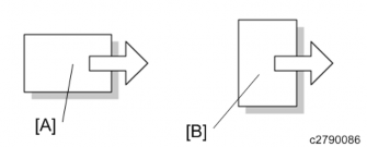
| SEF | Short Edge Feed |
| LEF | Long Edge Feed |

- Short Edge Feed (SEF)
- Long Edge Feed (LEF)
Trademarks
Microsoft®, Windows®, and MS-DOS® are registered trademarks of Microsoft Corporation in the United States and /or other countries.PostScript® is a registered trademark of Adobe Systems, Incorporated.
PCL® is a registered trademark of Hewlett-Packard Company. Ethernet® is a registered trademark of Xerox Corporation.
PowerPC® is a registered trademark of International Business Machines Corporation.
Other product names used herein are for identification purposes only and may be trademarks of their respective companies. We disclaim any and all rights involved with those marks.
PRODUCT INFORMATION
| RE V IS ION H IST ORY | ||
| Page | Date | Added/ Updated/ New |
| None |
Product Information
1. PRODUCT INFORMATION
1.1 PRODUCT OVERVIEW
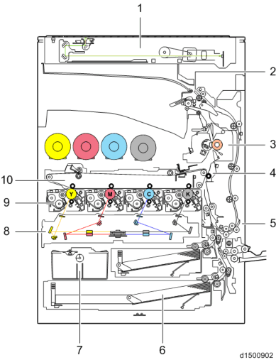
1.1.1 COMPONENT LAYOUT

| No. | Description | No. | Description |
| 1 | Scanner Unit | 6 | Paper Feed Unit |
| 2 | Paper Exit Unit | 7 | Waste Toner Unit |
| 3 | Fusing Unit | 8 | Laser Exposure Unit |
| 4 | Paper Transfer Unit | 9 | PCDU |
| 5 | Duplex Unit | 10 | Image Transfer Unit |
SM 1-1 D146/D147/D148/D149/D150
Product Overview
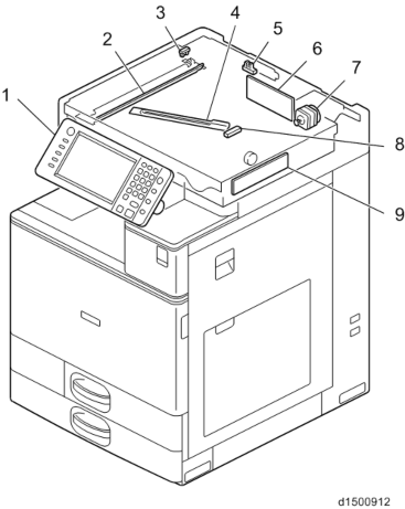
Scanner Unit

| No. | Description | No. | Description |
| 1 | Operation Panel | 6 | Scanner Input/Output (SIO) board |
| 2 | Scanner lamp Unit (LED) | 7 | Scanner motor |
3 | Scanner Home Position sensor | 8 | Auto Paper Size detection (APS) sensor |
4 | Anti-condensation heater (Scanner heater) *1 | 9 | Sensor Board Unit (SBU) |
| 5 | DF Position Sensor |
*1 Option
D146/D147/D148/D149/D150 1-2 SM
Product Overview
Product Information
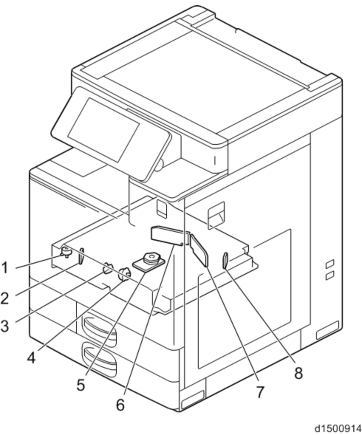
Laser Exposure Unit

| No. | Description | No. | Description |
| 1 | Skew motor | 5 | Polygon mirror motor |
| 2 | Synchronizing detector board: M/Y-S | 6 | LD Drive Board (M/Y) |
| 3 | Skew motor | 7 | LD Drive Board (Bk/C) |
4 | Skew motor | 8 | Synchronizing detector board: Bk/C-S |
SM 1-3 D146/D147/D148/D149/D150
Product Overview
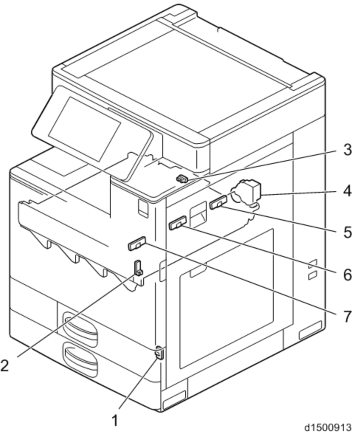
Image Transfer Unit

| No. | Description |
| 1 | Interlock switch: Front cover (LD Safety Switch) |
| 2 | Interlock switch: Duplex Unit (LD Safety Switch) |
| 3 | Imaging Temperature Sensor (Thermistor) |
| 4 | TM/P sensor shutter solenoid |
| 5 | TM/P sensor (rear) |
| 6 | TM/P sensor (center) |
| 7 | TM/P sensor (front) |
D146/D147/D148/D149/D150 1-4 SM
Product Overview
Product Information
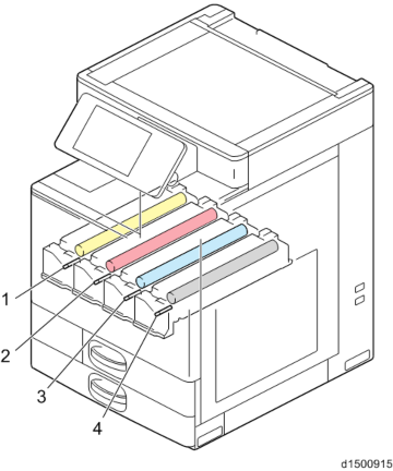
PCDU

| No. | Description | No. | Description |
| 1 | PCDU (Y) | 3 | PCDU (C) |
| 2 | PCDU (M) | 4 | PCDU (Bk) |
SM 1-5 D146/D147/D148/D149/D150
Last edited:
