
Installation
- Return the paper feed tray to the machine.
- Attach the decals as shown below.

[A]: Tray number decal : Paper size decal

- The tray number decal and paper size decal are packaged together with the machine.

[*]Connect the power cord to the machine.

- A stabilizer is attached to the machine when it is shipped. Do not remove it.

[*]Set the paper, and check that the paper size set in the paper feed tray is displayed on the operation panel.
[*]Adjust the registration for the paper feed unit.
SP1-002-004 (Side-to-Side Registration Paper Tray 3)
Changing the paper size
Paper size is set as shown below when the machine is shipped from the factory. NA: LT LEFEU.AA.CHN: A4 LEF
The paper size can be changed to A4 or LT.
- Pull out the left tray and right tray.
- Right tray side fence (front), [A], right tray side fence (rear) and right tray end fence [C]
×3)


Installation
[*]Attach the fences to the required position (A4 or LT).
[*]Make sure that the spring [A] is attached.

[*]Left tray side fence (front) [A] and left tray side fence (rear)×2)

[*]Attach the fences to the required position (A4 or LT).

[A]: A4 position (Holes are visible) : LT position (Holes are hidden)
[*]Set the SP SP5-181-007 0: A4, 1: LT
LCIT RT3030
Installation
ACCESSORY CHECK
Description Q’ty Screws – M3 × 6 1 Tapping screw – M3 × 6 1 Connecter Cover 1 Rating label 1 Joint Bracket 1 Harness 1

INSTALLATION PROCEDURE

- When installing this option, turn the power of the machine off, and unplug the power plug from the wall socket.
- If it is installed when the power is on, it will result in an electric shock or a malfunction.

- Before installing this option, first attach the “Paper Feed Unit PB3160” or “LCIT PB3170”.
- Remove the orange tape and retainers.
- Remove the enclosed items (fixing screws, etc.).
- Covers on the right of the paper feed table (8).

- Attach the connecting pins [A] to the front and rear on the right of the paper feed table.
- Attach the brackets [A], at the positions of the connecting pins ( ×4).

[*]Paper feed table rear covers [A]×2).

Installation
[*]Clamp the harness [A].

[*]Clamp the harness

[*]Attach the paper feed table rear cover.
[*]Attach the hook of the side LCT to the bracket.

[*]Connect the cable [A] of the side LCT to the machine×1).

[*]Attach the cable cover [A]×1).
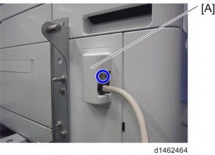
[*]Push the side LCT towards the machine.

Installation
[*]Turn the power switch ON.
[*]Set the paper, and check that the paper size set in the paper feed tray is displayed on the control unit.
[*]Do the registration adjustment for the large capacity tray. SP1-002-007 (Side-to-Side Registration Large Capacity Tray)
Changing the Paper Size
Paper size is set as shown below when the machine is shipped from the factory. NA: LT LEF
EU.AA.CHN: A4 LEF
The paper size can be changed to A4, LT, or B5.
1. Open the tray cover.

- Remove the upper screw at the front side fence, and after setting the side fence to the position of the paper (outer: A4 LEF, center: LT LEF, inner: B5 LEF), tighten the screw that was removed.
- Also change the rear side fence to the same size position.

- Change the paper size according to the new side fence position. SP5-181-017 (Size Adjust LCT)
0: A4, 1: LT, 2: B5
[*]CASTER TABLE TYPE M3
Installation
ACCESSORY CHECK
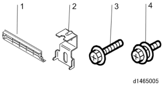
No. Description Q’ty 1 Right Lower Cover 1 2 Securing Bracket 2 3 Screws (M4 × 10) 2 4 Screw with Spring Washer (M4 × 10) 1
INSTALLATION PROCEDURE

- Removal of stabilizers must always be with the consent of the customer. Do not remove them at your own judgment.
- The machine must be held at the correct locations, and must be lifted slowly.
- If it is lifted with force, handled carelessly or dropped, it will result in an injury.
- If installing this option, turn the power to the machine off, and unplug the power plug from the wall socket.
- If it is installed when the power is on, it will result in an electric shock or malfunction.
- Be sure to join the machine and caster table to prevent equipment from falling over.
- If it is not joined, the machine will move or fall over, which will result in an injury.
- Attach the 3 locating pins.
- Holding the grips on the machine, align with the locating pin, and place the machine on the caster table.

- When you lift the machine, hold the lifting handles.
- In particular, do not lift it by holding the scanner unit, etc., (as it may deform). .
- Do not put the machine down on the caster table as a temporary resting place. This may cause the machine to deform. Always connect the machine and caster unit properly.
- Pull out the 2nd paper feed tray.
- Using a securing bracket, fix the machine to the paper tray unit (spring washer : screw: M4×10: 1).
- Attach the securing brackets [A] at 2 positions to left and right at the rear of the machine (screws: 1 each).
- Return the paper feed tray to the machine.
- Attach the 3 locating pins.
PLATEN COVER PN2000
ACCESSORY CHECK
Installation
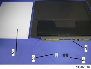
Check that you have the accessories indicated below.
No. Description Q’ty 1 Platen Cover 1 2 Platen Sheet 1 3 Feeler Guide 1 4 Stepped Screw 2
INSTALLATION PROCEDURE

- Unplug the machine power cord before starting the following procedure.
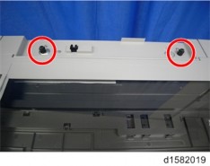
[*]Install the stepped screws× 2).
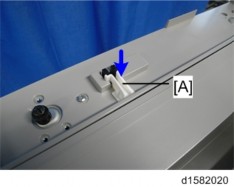
[*]Install the feeler guide [A].
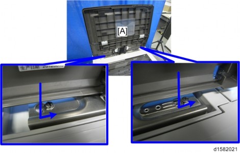
[*]Install the platen cover [A].
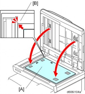
[*]Place the platen sheet [A] on the exposure glass.
[*]Line up the rear left corner of the platen sheet flush against corner on the exposure glass.
Installation
[*]Close the platen cover.
[*]Open the platen cover.
[*]Press the surface of the platen sheet gently to fix it on the platen cover securely.
