HOME PAGE | < Previous | Contents | Next >
Copy Adjustments: Printing/Scanning
4.16 COPY ADJUSTMENTS: PRINTING/SCANNING
4.16.1 OVERVIEW
Perform these adjustments after replacing any of the following:
Scanner Wire
Lens Block/SBU Assembly
Scanner Drive Motor
Polygon Mirror Motor
Paper Side Fence
Memory All Clear
4.16.2 PRINTING
Replacement and Adjustment
Replacement and Adjustment
Replacement and Adjustment
1. Make sure paper is installed correctly in each paper tray before you start these adjustments.
2. Use the Trimming Area Pattern (SP2-109-1, No. 14) to print the test pattern for the following procedures.
Registration - Leading Edge/Side-to-Side

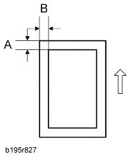
1. Check the leading edge registration [A] for each paper type and paper feed station, and adjust it with following SP modes.
SP No. | Specification | |
Tray: Plain | SP1-001-1 | 0 ±9.0 mm |
Tray: Thick 1 | SP1-001-2 |
SM 4-109 D129/D130
Copy Adjustments: Printing/Scanning
Rev. 12/27/2012
SP No. | Specification | |
Tray: Thick 2 | SP1-001-3 | |
By-pass: Plain | SP1-001-4 | |
By-pass: Thick 1 | SP1-001-5 | |
By-pass: Thick 2 | SP1-001-6 | |
Duplex: Plain | SP1-001-7 | |
Duplex: Thick 1 | SP1-001-8 |
2. Check side-to-side registration [B] for each paper feed station, and adjust with the following SP modes.
SP No. | Specification | |
By-pass | SP1-002-1 | 0 ±4.0 mm |
Tray 1 | SP1-002-2 | |
Tray 2 | SP1-002-3 | |
Tray 3 | SP1-002-4 | |
Tray 4 | SP1-002-5 | |
LCT | SP1-002-6 | |
Duplex | SP1-002-7 |
D129/D130 4-110 SM