HOME PAGE | < Previous | Contents | Next >
Rev. 09/11/2012

4.4 SCANNER
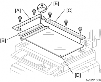
4.4.1 EXPOSURE GLASS
1. Glass cover [A] ( x 2)
2. ARDF exposure glass [B]
3. Rear scale [C] ( x 3)
4. Exposure glass with left scale [D]
Position the white marker [E] at the rear-left corner and the black or blue marker at the front-left corner when you reattach the ARDF exposure glass.
4.4.2 SCANNER EXTERIOR PANELS AND OPERATION PANEL
Operation panel
1. Remove the Operation Panel ( 4.3.6)
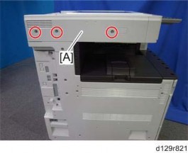
Scanner left cover

1. Scanner left cover [A] ( x 3)
D129/D130 4-12 SM
Replacement and Adjustment
Replacement and Adjustment
Replacement and Adjustment