Detailed Descriptions
Toner starts to adhere to the drum in proportion to the potential when the value of potential becomes more than Vb. The value (coefficient) which shows the relation between the potential and the amount of adhesion is called development gamma.

In addition to the development gamma and the potential, the toner density in the developer needs to be controlled. This is done to maintain the proper toner density (the amount of toner adhesion). The target figure for the toner density in the developer is called Vref.
Process control is done as shown in the following chart, which includes development gamma determination, Vref correction, and LD power control.

This decides the charge voltage and development bias
A4 LEF, LT LEF, B5 LEF, and A5 LEF (select with UP mode, default is A4 LEF)
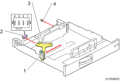
Size is detected by the detection patterns of knobs 1, 2, 3, and 4. Tray set is detected by another switch.
If there has been a change in the pattern, "MFP tray automatic size detection" control is performed continuously.
If the paper size is selected manually by user setting, the automatic size detection is overridden.
Detailed Descriptions
Detailed Descriptions
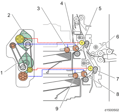
The bypass transport roller is driven by the bypass/duplex motor, and the registration roller is driven by the registration motor.
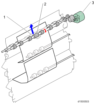
Detailed Descriptions
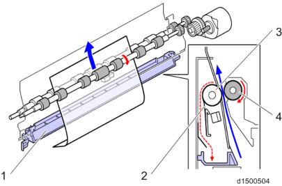
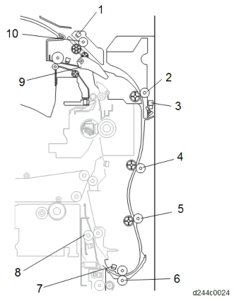
- Execution result example (In order of YMCK from left)
- Factory default (SP default): [00,00,00,00]
- Starting adjust: [99,99,99,99]
- Fail Vsg adjust(Y): [21,99,99,99]
- Error of Development gamma Max(C): [99,99,55,99]
- Succeeded: [11,11,11,11]
The Process Control Procedure
The potential of the unexposed drum is called the electrified potential (Vd), whereas the potential when toner starts to adhere to the drum is called the development bias (Vb).Toner starts to adhere to the drum in proportion to the potential when the value of potential becomes more than Vb. The value (coefficient) which shows the relation between the potential and the amount of adhesion is called development gamma.

In addition to the development gamma and the potential, the toner density in the developer needs to be controlled. This is done to maintain the proper toner density (the amount of toner adhesion). The target figure for the toner density in the developer is called Vref.
Process control is done as shown in the following chart, which includes development gamma determination, Vref correction, and LD power control.

Electrified Potential / Development Bias, Vref Correction
Electrified Potential/ Development Bias and Vref Correction are done with the following method. The operation time differs depending on the line speed.Adjusting the ID sensor Vsg
The machine adjusts the LED strength of the ID sensor so that the value of Vsg (the charge which is detected from the background on the Transfer Belt) will be in the range of 4.0V ±0.5V. When Vsg is detected as not within the target range three times, SC370 (ID sensor error) will be detected.
- SP3-320-031/032/033 (Vsg Error Counter)
- SP3-320-013 (Vsg Upper Threshold)
- SP3-320-014 (Vsg Lower Threshold)
Agitating the Developer (5 seconds)
Detailed Descriptions
The machine agitates the developer and reads the TD sensor output.
- SP3-539-001 (Dev Agitating Time :Set)
Creating patterns, detecting the density
5 patterns are created on the transfer belt and detected by each ID sensor, with the Charge/ Development Bias adjusted for each pattern.
The ID sensor contains an LED and two types of photo detector. The sensor detects the reflection from the LED with the positive photo detector (REG) [A] and the diffusion photo detector (DIF) [C].

[*]Determining Vtref from the Development Gamma
This decides the charge voltage and development bias
LD Power Control
LD Control is set with SP3-600-002(Process Control/ Select ProCon: LD Control).To use a fixed LD Power
Change the SP setting to [Fixed]. LD strength is fixed with SP2-221-001 to 004.To control LD Power by Process Control (Default)
- The LD power is determined by process control.
- The LD strength is adjusted based on a table which is determined by the Development Bias Control and Vref Correction.
Toner Supply Control
The Toner Supply Type can be selected with SP3-400-001 to 004 (Toner Supply Type).
0: Fixed (Fixed supply method)
The toner supply time is calculated based on the supply rate of SP3-440-001 to 004 (Fixed Supply Mode: Fixed Rate).2: PID (Proportion Integral Differential)
The amount of toner supply is calculated based on the pixel information and TD sensor information.4: DANC (Divided Active Noise Control) (Default)
Conventional PID method + active noise control. It controls the timing to supply the developer to minimize uneven developer density in the development unit.
Developer Initial Setting
When a new PCDU is set in the machine, the machine automatically detects it and enters the developer initial setting mode. The machine then detects thecount which is an output from the TD sensor. The developer initial setting is done as follows.
Starting the developer initial setting mode
The new unit detection mechanism triggers the developer initial setting mode.Agitating the developer
The machine rotates the development roller and transport coil to agitate the developer for 30 seconds.Detecting the
While agitating the developer, the machine detects the output from the TD sensor, and stores this output as the initialcount (Initial value) count.
Calculating Vt
The machine calculates Vt using the difference of the currentcount while referring to the initial count through SP.
Forced toner supply (only when newly installing the machine)
- This step is required only when the machine is newly installed because there is no toner in the toner transport route.
Detailed Descriptions
When the developer initial setting is successfully completed, the machine stores the calculated Vt as Vtref. The Vtref is used as a reference the next time the machine performs an initial developer setting.
SC360-01 through -04 appears if the results of step 3 are as follows:- The
count is equal or exceeds the threshold (6480 [counts]).

- The
count does not match the target threshold (5800 – 6380 [counts]) three times consecutively.

Process Control and MUSIC are forcibly done after developer initial setting when a PCDU is replaced.
MUSIC (AUTOMATIC COLOR REGISTRATION CORRECTION)
Correction Timing
The machine creates correction patterns, measures the image position by reading the correction patterns, and corrects the writing position.
Operative Condition Notes
1Power switch just turned on, or recovering from the energy save mode Mode b or Mode a is done See notes *1 and *2 below.
2When printing (when the temperature has changed by a certain amount since the previous job ended, or when the number of pages printed becomes more than a set number)
Mode b is done
3End of printing (when the temperature has changed by a certain amount since the previous job ended, or when the number of pages printed becomes more than a set number)
Mode b is done
4Front cover opening/ closing (when the temperature has changed by a certain amount since the previous job ended)
Mode b is done
5Waiting (when the temperature has changed by a certain amount since the previous job ended, and when the number of pages printed becomes more than a set number)
Mode b is done
6When the machine detects a new PCDU, and/or image transfer belt
Mode a is done
*1 Mode a: adjusted two times
*2 Mode b: adjusted once
Executing MUSIC Manually
To operate modes a, b, and c manually, use the following SPs.
- SP2-111-001 (Mode a)
- SP2-111-002 (Mode b)
- SP2-111-003 (Mode c)
Do this SP after the laser unit is changed. - SP2-111-004 (Mode d)
Mode d is the same as doing mode c then mode a. Normally in the field, we should only use mode d.
- Color registration errors can be corrected only by the mode d when the error is large.
[Color Registration] in User Tools (SP2-111-004)
Correction with higher accuracy can be performed by contacting the image transfer roller and executing MUSIC in a condition that is almost the same as during actual printing. This process is called ‘contact MUSIC’.
Contact MUSIC can be done manually by executing HOME screen -> User Tools icon -> Machine Features -> Maintenance -> Color Registration (SP2-111-004).
When the Imageable Area Extension Unit is installed, the MUSIC sensor is in the printing area. Therefore, the image transfer roller cannot be contacted and execution of MUSIC becomes the same as the previous machine.
Items MP C2003/C2503/C2011 MP C2004/C2504 Normal Operation rough adjustment -> fine adjustment only rough adjustment -> fine adjustment
-> contact MUSICWith Imageable Area Extension Unit
rough adjustment -> fine adjustment only
rough adjustment -> fine
* Same as the previous machine
Detailed Descriptions
Execution time varies from model to model.
Items MP C2003/C2503/C2011 MP C2004/C2504 Execution time About 22 sec. About 29 sec.
MUSIC Error Judgment
When MUSIC is done, the results must be checked for each color. SP2-194-007 shows whether MUSIC was OK or NG, and SP2-194-010 to 012 show the details of the result.
- Color registration errors can be corrected only by the mode d when the error is large.
- SP2-194-007 (Execution Result)
Detection Result
Meaning0 Success 1 Failure
- SP2-194-010 (Error Result: C)
- SP2-194-011 (Error Result: M)
- SP2-194-012 (Error Result: Y)
Detection Result
Meaning0 MUSIC not executed
1Correction Succeeded: Sampling is conducted correctly and the correction is completed 2 Sampling Failed (When the MUSIC pattern failed to be detected)
3Detection Patterns Lack (When the number of lines detected is smaller than the fixed number)
4The sampled data is beyond the correction range. (Calculated correction value is just out of rage) 5 The sampled data is beyond the correction range. Correction Operation Outline
- The machine corrects the ID sensor output by Vsg adjustment
- The machine creates the MUSIC pattern on the transfer belt with toner of each color.
- The machine reads the MUSIC pattern on the transfer belt and detects the positions of the line patterns.
- The machine calculates the amount of color registration or skew from the detected positions.
- The machine determines the correction for the color registration, by calculating the required main scan magnification shift, main scan magnification deviation, main scan registration shift, skew correction value, and sub scan registration shift from the detected positions.
REAL TIME PROCESS CONTROL
During printing, 5 mm patterns are created outside the normal imaging area on the transfer belt, and the image density is corrected in the real time, to improve printing of solid areas. However, note that if the optional Imageable Area Extension Unit is installed, this process is disabled.

Normally, the real time control is done once every 10 sheets, but it could be done once every 5 sheets depending on the density detection level.
The frequency depends on the following SPs.
- SP3-301-001: RTP Pattern:Set:Create Intrvl:BW
- SP3-301-002: RTP Pattern:Set:Create Intrvl:FC
To see the latest result, check the following SPs. If there is an error, the result will not be updated. - SP3-300-001 to 004 RTP Pattern
isp:M/A(Latest):Each Color
- SP3-300-001 to 004 RTP Pattern
isp:M/A(Target):Each Color
Detailed Descriptions
IBACC
Outline
IBACC (Image transfer belt type of inner ACC) maintains the quality of gradation in the images. To do this, the machine makes a gradation pattern on the transfer belt, and measures variations in density between the middle to the highlight tone, which solid printing control cannot correct perfectly. The machine feeds back variations in the density to the image-processing parameters (the digital gamma correction table).
Operation Timing
IBACC must be done in the shortest time possible, in cooperation with process control. This is because the process requires time to adjust. If the ON/OFF setting of IBACC operation
(SP3-600-030) is ON, IBACC is done at the time of normal process control. If the setting is OFF, the IBACC is not done.
Before the IBACC procedure, the machine determines whether IBACC can be done, based on the engine condition. If there is an error in the latest process control, the following IBACC is considered to be unnecessary.
Patch Pattern
16x16 patterns are created. The order of the tones depends on the image processing layout. There are patterns for 600 dpi and 1200 dpi.

SP Descriptions
SP2-111-001 (Forced Line Position Adj.: Mode a)
Executes MUSIC mode a ( fine-tune x 2)SP2-111-002 (Forced Line Position Adj.: Mode b)
Executes MUSIC mode b ( fine-tune x 1)SP2-111-003 (Forced Line Position Adj.: Mode c)
Executes MUSIC mode c (rough-tune x 1)SP2-111-004 (Forced Line Position Adj.: Mode d)
Executes MUSIC mode d (rough-tune then fine-tune)SP2-194-007 (MUSIC Execution Result: Execution Result)
Displays the execution results of MUSIC. 0: Completed successfully, 1: FailedSP2-194-010,-011, and -012 (MUSIC Execution Result:Error Result: C, M, Y)
Displays the details of MUSIC results for each color.SP3-011-001 (Manual ProCon :Exe: Normal ProCon)
Executes Pro-Con.SP3-011-002 (Manual ProCon :Exe: Density Adjustment)
Executes toner density adjusting Pro-Con.SP3-011-003 (Manual ProCon :Exe: ACC RunTime ProCon)
Executes pre-ACC Pro-Con.SP3-011-004 (Manual ProCon :Exe: Full MUSIC)
Executes Pro-Con / full MUSIC.SP3-011-005 (Manual ProCon :Exe: Normal MUSIC)
Executes Pro-Con / normal MUSIC.SP3-012-001 to 010 (ProCon OK?: Front)
Displays the history for past 10 times of ProCon results code detected by the front TM/ID sensor. The code is 2 digits per color from left, in the order of YMCK.SP3-012-011 to 020 (ProCon OK?: Center)
Displays the history for past 10 times of ProCon results code detected by the center TM/ID sensor. The code is 2 digits per color from left, in the order of YMCK.SP3-012-021 to 030 (ProCon OK?: Rear)
Displays the history for past 10 times of ProCon results code detected by the rear TM/ID sensor. The code is 2 digits per color from left, in the order of YMCK.SP3-400-001 to 004 (Toner Supply Type: Select; Bk, C, M, Y)
Selects the toner supply mode. 0: FIXED, 2: PID, 4: DANK
Detailed Descriptions
SP3-530-001 to 008 (PowerON ProCon :Set)
Specifies the non-use time setting, temperature, relative humidity, absolute humidity or page interval as the threshold of process control execution determination at power on.SP3-531-001 to 004 (Non-useTime Procon :Set)
Specifies the non-use time setting, temperature, relative humidity, absolute humidity or page interval as the threshold of process control execution determination for during the
stanby-mode.SP3-533-001 (Interrupt ProCon :Set: Interval:Set:BW)
Specifies the number of sheets interval for Interrupt Pro-Con (BW).SP3-533-002 (Interrupt ProCon :Set: Interval
Displays the number of sheets interval for Interrupt Pro-Con (BW).isp:BW)
SP3-533-003 (Interrupt ProCon :Set: Corr(Short):BW)
Specifies the correcting coefficient (Short) of number of sheets interval for Interrupt Pro-Con (BW).SP3-533-004 (Interrupt ProCon :Set: Corr(Mid):BW)
Specifies the correcting coefficient (Mid) of number of sheets interval for Interrupt Pro-Con (BW).SP3-533-011 (Interrupt ProCon :Set: Interval:Set:FC)
Specifies the number of sheets interval for Interrupt Pro-Con (FC).SP3-533-012 (Interrupt ProCon :Set: nterval
Displays the number of sheets interval for Interrupt Pro-Con (FC).isp:FC)
SP3-533-013 (Interrupt ProCon :Set: Corr(Short):FC)
Specifies the correcting coefficient (Short) of number of sheets interval for Interrupt Pro-Con (FC).SP3-533-014 (Interrupt ProCon :Set: Corr(Mid):FC)
Specifies the correcting coefficient (Mid) of number of sheets interval for Interrupt Pro-Con (FC).SP3-534-001 (JobEnd ProCon :Set: Interval:Set:BW)
Specifies the number of sheets interval for Job end Pro-Con (BW).SP3-534-002 (JobEnd ProCon :Set: Interval
Displays the number of sheets interval for Job end Pro-Con (BW).isp:BW)
SP3-534-003 (JobEnd ProCon :Set: Corr(Short):BW)
Specifies the correcting coefficient (Short) of number of sheets interval for Job end Pro-Con (BW).SP3-534-004 (JobEnd ProCon :Set: Corr(Mid):BW)
Specifies the correcting coefficient (Mid) of number of sheets interval for Job end Pro-Con (BW).SP3-534-011 (JobEnd ProCon :Set: Interval:Set:FC)
Specifies the number of sheets interval for Job end Pro-Con (FC).SP3-534-012 (JobEnd ProCon :Set: Interval
Displays the number of sheets interval for Job end Pro-Con (FC).isp:FC)
SP3-534-013 (JobEnd ProCon :Set: Corr(Short):FC)
Specifies the correcting coefficient (Short) of number of sheets interval for Job end Pro-Con (FC).SP3-534-014 (JobEnd ProCon :Set: Corr(Mid):FC)
Specifies the correcting coefficient (Mid) of number of sheets interval for Job end Pro-Con (BW).SP3-539-001 (Dev Agitating Time :Set: Time) Specifies the developer agitating time.
SP3-600-002 (Select ProCon: LD Control)
Specifies the LD control mode. 0:OFF, 1:ONSP3-600-030 (Select ProCon: IBACC:ON/OFF)
Specifies ON/OFF of IBACC. 0: OFF, 1: ON
Detailed Descriptions
PCDU (PHOTO CONDUCTOR AND DEVELOPMENT UNIT)
OVERVIEW
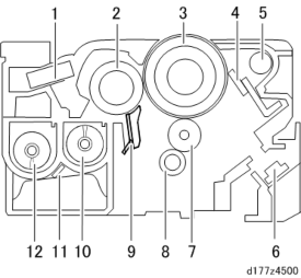
No. Description No. Description 1 Inner pressure adjustment filter 7 Charge roller 2 Development roller 8 Cleaning roller (charge roller) 3 OPC drum 9 Doctor blade 4 Cleaning blade 10 Developer supply coil 5 Toner collection coil 11 TD sensor
6Discharge lamp (installed on the main machine)
12
Developer collection coilMECHANISM (PCU)
Drum Drive
Bk and CMY are both driven by motor.
PCU Drive source Bk PCU motor: Black / ITB drive motor* CMY PCU motor: CMY
* The PCU motor: Black / ITB drive motor is used to drive both the image transfer unit and the waste toner bottle.
Charge
This device uses a charge roller for all four colors to reduce generation of ozone.
The charge roller, which is a rubber-covered roller that has a metal shaft, rotates in the forward direction contacting the drum [A], and applies a charge to the drum surface uniformly.

When the charge roller is dirty, an uneven charge is generated, so a cleaning roller [C] always contacts the charge roller.
Drum Cleaning
Residual toner on the drums after image transfer is recovered by a cleaning blade [A]. The cleaning blade is installed counter to the drum rotation in contact with the drum, and scrapes toner off.

Detailed Descriptions
[*]MECHANISM (DEVELOPMENT)
Development System
A dry two-component magnetic brush development system is used.
The dry two-component magnetic brush development system gives a suitable electrostatic charge to the toner using magnetic particles called carriers which form a magnetic brush due to their magnetism, and cause toner to adhere electrostatically to the drum surface.
Agitation System
This device uses a double-coil agitation system (twin-shaft environment development system). Toner transported from the toner cartridge to the development unit will be agitated with the developer by two toner transport coils [A] and will be delivered to the development roller.
The amount of developer adhering to the development roller is controlled by a doctor blade , and supplies toner to the surface of the photoconductor unit.

TD Sensor
In the TD sensor (also called thesensor), there is an ID chip storing the machine identification information, the running distance information of Development unit and PCU, and other information used by image density control.
ID chip
PCDU replacement information and toner density information are stored. In the ID chip, the following data is stored.
- Model series ID
- New PCDU information
- Color information
- Developer replacement information
- PCU replacement information
- TD sensor serial no., date of manufacture
- Date of unit installation
- Unit total counter at installation (no. of sheets, travel distance)
- Date of unit operation
- Unit total counter during operation (no. of sheets, travel distance)
- Unit parts information
- Total counter
- Total color counter
Pressure Release Filter
To prevent scattering of toner, the air pressure in the development unit is released via a filter.
Development Drive
A gear for developer coil rotation is provided on the front side of the unit (downstream side).
Drive source for Bk Drive source for C, M, Y PCU motor: Black / ITB drive motor Development motor: CMY
The PCU motor: Black / ITB drive motor is also used for the image transfer unit and waste toner bottle. Drive is switched by the development solenoid.
Development Bias
Applied from the development power pack via a plate spring on the front cover of the PCDU.
Detailed Descriptions
[*]TONER SUPPLY
OVERVIEW
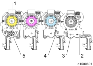
No. Description No. Description 1 Toner bottle drive motor 4 Toner end sensor 2 Agitator 5 Toner supply motor 3 Sub-hopper
Toner is supplied by a Hi-Act (High Accuracy and Clean Toner) cartridge + sub-hopper.
MECHANISM
Toner Supply (Toner Cartridge - Sub-hopper)
When the toner cartridge is set, the transport nozzle on the side of the unit is inserted into the bottle (Hi-Act system).
When the toner supply motor drives and the piezoelectric sensor in the sub-hopper detects there is no toner, the bottle drive motor rotates. The rotation of the bottle drive motor is transmitted to a transport coil via a drive gear, and toner in the bottle is transported horizontally. Due to the coil transport, stable toner supply/enhanced supply precision/reduction of residual toner are achieved.

[A]: Before setting : After setting [C]: Toner path
No. Description No. Description 1 Toner bottle 7 Transport nozzle 2 Coil spring 8 Coil spring 3 Shutter holder 9 Toner transport coil 4 Seal 10 Drive gear 5 Shutter 11 Rocking spring 6 Shutter 12 sub-hopper
Toner transported by the coil falls directly into the sub-hopper via the transport pipe.
To prevent toner from remaining, the rocking spring in the transport pipe moves up and down together with the coil.

Detailed Descriptions
[A]: Rocking spring
Toner Bottle ID Chip
A contact type ID chip is provided in each toner bottle which stores residual toner and various toner counters, toner end history, and model serial number.
Data read and write to the ID chip contact board is performed by contact with the ID chip contact board installed in the machine.
Toner Supply (Sub-hopper - Development Unit)
The sub-hopper can hold Bk: 24.7 cc (equivalent to 230 sheets of 5% chart), or Color: 19.3 cc (equivalent to 150 sheets of 5% chart) of toner.
Toner which has fallen into the sub-hopper is homogenized by an agitator (Mylar sheet: 2 for BK, 1 for each color).
After being horizontally transported by the coil, toner in the sub-hopper falls directly into the development unit.

[A]: Sub-hopper: CMY : Sub-hopper: Bk
- Transport by the Mylar sheet
- Transport horizontally by the coil
- Vertical drop to the development unit
- Transport by the Mylar sheet
- Transport horizontally by the coil
- Vertical drop to the development unit
Drive
To shorten the recovery time after bottle replacement, the toner cartridge and sub-hopper are driven separately.
The sub-hopper is driven by a stepping motor to reduce supply variations.
Toner Near End/ Toner End Detection
In this device, there are two types of toner near end status.
The detection conditions and detection operation for each status are shown in the following table.
Control overview
Status Control panel message Detection conditions If the residual amount in the toner cartridge falls below SP3-110-001
Estimated toner end SP3-101-001 to 004="2"
Control panel banner display:
<Toner Cartridge is almost empty. Prepare toner cartridge replacement(s).>to 004 (Near End Thresh) (Default: K 65g, CMY 45g)
The lesser of the "toner residual amount computed from the toner supply motor drive time" and the
"toner residual amount computedfrom the pixel count" is taken as the toner residual amount. Status Control panel message Detection conditions
Definite toner near end
SP3-101-001 to 004="1"
Control panel banner display:
<Toner Cartridge is empty. Printing will be suspended soon.
Replace the cartridge.>If "the toner cartridge residual amount falls below specification" and "the toner end sensor in the sub-hopper has detected toner end"
Remarks:
When toner end is detected, to use up all the toner in the cartridge, the toner cartridge is rotated for 5 seconds (full use control).
After no toner is detected again, the status becomes definite toner near end.
Toner end
Control panel pop-up display (alert screen):
<Toner has been depleted. Replace Toner Cartridge.>Toner end is defined by the following conditions (1) or (2):
(After definite toner near end, count is begun).- Determination by number of sheets and pixel count
- Determination by Vt output (not related to definite toner near end)
Detailed Descriptions
Control details Estimated toner near end
- The toner residual amount Z (SP3-102-021 to 024) is taken as the lesser of the toner residual amount Z1 computed from the toner supply motor drive time (SP3-102-001 to
- and the toner residual amount Z2 computed from the pixel count (SP3-102-011 to 014).
- If the condition, toner residual amount Z (SP3-102-021 to 024) < near end residual amount threshold value (SP3-110-001 to 004) is satisfied, this is taken as the estimated toner near end.
Definite toner near end Preconditions
- The toner residual amount Z (SP3-102-021 to 024) is taken as the lesser of the toner residual amount Z1 computed from the toner supply motor drive time (SP3-102-001 to
- and the toner residual amount Z2 computed from the pixel count (SP3-102-011 to 014).
- If the condition, toner residual amount Z (SP3-102-021 to 024) < sensor near end residual amount threshold value (SP3-120-001 to 004) is satisfied, toner end sensor detection is begun to determine the definite end. (When the toner residual amount is more than the threshold value, determination by the toner end sensor is not performed).
Sensor detection
- The toner end sensor detects the sensor output every 200 ms while the polygon motor is ON, and determines whether toner is present or not from the latest 10 counts.
- The determination result is stored in the "no toner counter (SP3-121-001 to 004)". To prevent clearing due to erroneous detection, the counter is reset if the toner end sensor detects "toner remaining" 4 times in a row.
- If the condition "no toner counter (SP3-121-001 to 004) > sensor near end determination threshold value (SP3-122-001 to 004) is satisfied, full use control which rotates the toner bottle for a certain time (SP3-163-001) is performed, and toner presence/absence determination by the toner end sensor is performed again.
- If no toner is detected after full use control determination, it is taken as definite toner near end.
Operation after changing the status to definite toner near end
- After changing the status to definite toner near end, sheet counter and pixel counter increment is begun to detect toner end.
SP3-133-011 to 014 (TE Detect :Set Page Cnt:K, C, M, Y) SP3-133-031 to 034 (TE Detect :Set Pxl Cnt:K, C, M, Y)
Operation during definite toner near end
- When the toner supply motor drives and the toner end sensor detects no toner, the toner bottle motor drives for 2 seconds.
- If "toner remaining" is detected 4 times in a row, according to the ID chip data on the toner bottle SP3-101-001 to 004 (Toner Status
isp) display "10" or "2" (estimated toner end).
- When it comes under the condition of Toner end pattern (1) and (2) (mentioned below), the status becomes toner end.
- After the toner bottle is replaced during definite toner near end, the machine does not execute the toner end judgement until the toner bottle motor drives for 40 or more seconds totally.
Toner end
Pattern (1): Determination by paper sheet counter/pixel counter
The total sheet counter and pixel counter values after definite toner near end are compared with the threshold values.
If the following "(evaluation method A=TRUE) and (evaluation method B=TRUE) or
Detailed Descriptions
(evaluation method C=TRUE)" is satisfied, it is determined as toner end. - Determination method A: Sheet counter (SP3-133-011 to 014) > Sheet counter threshold value (min)
- Determination method B: Sheet counter (SP3-133-011 to 014) > Sheet counter threshold value (max)
- Determination method C: Pixel counter (SP3-133-031 to 034) > Pixel counter threshold value
Pattern (2): Determination by Vt output
When the deviation between the TD sensor output value and TD sensor target value has become large, it is taken as toner end. - After definite toner end has been determined
The difference between the output of the TD sensor (Vt: SP3-210-001 to 004) and the target value of the TD sensor (Vtref: SP3-230-001 to 004) is computed as the delta Vt, and values of the delta Vt larger than the threshold value (SP3-131-001) are integrated as "sigma delta Vt" (SP3-132-001 to 004).
If the integration value of "sigma delta Vt" is larger than the threshold value (SP3-132-002), it is determined to be toner end. - Before definite toner near end is determined (bottle full or estimated toner near end) The computation is done in the same way as for definite toner near end, but separate values for the delta Vt threshold value and "sigma delta Vt" threshold value are used.
- Delta Vt threshold value before toner near end: SP3-131-011
- Sigma delta Vt threshold value before toner near end: SP3-131-012
SP Descriptions
[*]SP3-101-001 to 004 (Toner Status
Displays the amount of toner remaining for each color. Uses a descending 10-step scale: 10: Full, 2: Estimated toner near end, 1: Definite toner end, 0: Toner endisp)
[*]SP3-110-001 to 004 (Near End Thresh)
Sets the threshold amount of judging near-toner end.
[*]SP3-102-001 to 004 (Toner Remain
Displays the remaining toner calculated from the motor running time.isp: Bottle Motor Bk, C, M, Y)
[*]SP3-102-011 to 014 (Toner Remain
Displays the remaining toner calculated from imaging size.isp: Pixel Bk, C, M, Y)
[*]SP3-102-021 to 024 (Toner Remaining: Display: Fill Amount Bk, C, M, Y)
Display the filler content of new bottle.
[*]SP3-120-001 to 004 (TE Sn Detect Thresh: Bk, C, M, Y)
Sets the starting threshold of the near-toner end detection by the toner end sensor.
[*]SP3-121-001 to 004 (TE Counter: Disp: Bk, C, M, Y)
Displays the number of times the toner end sensor detected toner end.
[*]SP3-122-001 to 004 (TE Sn NE Thresh: Bk, C, M, Y)
Sets the number of toner end detection to start near-toner end detection.
[*]SP3-163-001 (Bottle Drive: Set Rotation Time at Toner End)
Sets the empty turn time[ms] at almost toner-end.
[*]SP3-133-011 to 014 (TE Detect :Set Page Cnt:K, C, M, Y)
Displays the amount of sheets printed after toner near end is fixed.
[*]SP3-133-031 to 034 (TE Detect :Set Pxl Cnt:K, C, M, Y)
Displays the amount of toner used in cm2 after toner near-end is fixed.
[*]SP3-210-001 to 004 (TD.Sens:Vt
Displays the latest TD sensor output.isp: Current: K, C, M, Y)
[*]SP3-131-001 (Vt TE Thresh: Delta Vt Thresh)
Specifies the threshold to start adding the delta Vt after toner Near End.
[*]SP3-132-001 to 004 (Delta Vt Sum: Bk, C, M, Y)
Displays the integrated value of delta Vt.
[*]SP3-131-011 (Delta Vt Thresh BF NE)
Specifies the threshold to start integrating delta Vt before toner Near End.
[*]SP3-131-012 (Delta Vt Sum Thresh BF NE)
Specifies the threshold of delta Vt to check Toner End before toner Near End.
Detailed Descriptions
WASTE TONER
OVERVIEW

No. Description No. Description 1 Waste toner bottle full sensor 2 Waste toner bottle set sensor
MECHANISM
Waste Toner Bottle Set Detection
The waste toner bottle set sensor is at the rear of the waste toner bottle.
If the waste toner bottle is not set, this switch is OFF, so imaging is prohibited, and "Waste toner bottle is not set. Please contact service department." is displayed on the control panel.
Waste Toner Drive
Driven by the "PCU motor: Black / ITB drive motor".
Waste Toner Recovery Path (PCU/Image Transfer Unit)
Waste toner from the PCU and Image transfer unit is collected in the transport path at the front of the machine, and arrives at the entrance to the waste toner tank.
PCU waste toner transport path
Waste toner recovered by the cleaning blade is transported from the rear of the PCU to the transport path at the front of the machine by the waste toner transport coil.
Image transfer unit waste toner transport path
Waste toner recovered by the Image transfer cleaning unit is transported from the rear of the
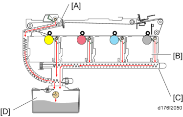
Image transfer cleaning unit to the transport path at the front of the machine by the waste toner transport coil.
[A]: Image transfer unit waste toner transport path : PCDU
[C]: PCU waste toner transport path [D]: Waste toner bottle
Waste Toner Bottle Full Detection
The waste toner bottle full sensor is at the top of the waste toner bottle. When the waste toner in the bottle has reached approximately 90%, the sensor lifts up a feeler, and an actuator blocks the waste toner bottle full sensor. After sensor detection, the remaining number of days of use is decremented from 18 by the pixel counter.
Full detection flow
- When waste toner reaches approximately 90% of the bottle capacity, the full sensor switches ON.
- When the waste capacity sensor switches ON, the days remaining counter is decremented from 18.
- Days remaining counter: At 15 days to go, a @Remote warning is given (only in models with @Remote connection).
- Days remaining counter: At 5 days to go, a control panel message (Waste toner bottle is nearly full. Please contact service department.) is displayed. (Nearly full)
- Days remaining counter: At 0 days to go, a control panel warning is displayed, and the machine stops.
- After the full sensor switches ON, before nearly full, if the waste toner bottle full sensor has been switched OFF, it is determined that the waste toner bottle has not been replaced, and countdown of the days remaining counter continues.
- The days remaining counter starts computing when a new bottle is detected, and displays the days remaining, whose upper limit is 255 and lower limit is 18, until the waste toner
Detailed Descriptions
bottle full sensor is first switched ON. - After the full sensor was first switched ON, the days remaining which is computed from when the sensor switched ON is displayed (upper limit is 18)
- When the bottle is replaced before the machine detects a full waste toner bottle and stops printing, it is necessary to reset PM counters manually (SP3-701-142).
- When the bottle is replaced after the machine stopped due to detecting a full waste toner bottle, it is not necessary to reset PM counters. If the counters are reset, the replace counter will count up twice.
SP descriptions
[*]SP3-701-142 (Manual New Unit Set: Waste Toner Bottle)
Enables/disables the new unit detection function. When this function is ON, the machine automatically resets the PM counter when a new unit is detected.
Waste Toner Cover
The latch which existed with the previous machine has been removed for this machine.
The waste toner cover is opened by pulling the 1st paper tray, and inserting a finger into the gap (red circle) shown below.

The waste toner cover of the previous machine (MP C2003/C2503/C2011) is opened by pressing it with your fingers.

IMAGE TRANSFER AND PAPER TRANSFER
OVERVIEW
Image Transfer Unit
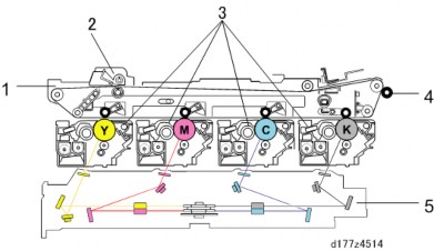
No. Description No. Description 1 Image transfer unit 4 Paper transfer roller 2 Image transfer belt cleaning unit 5 Laser exposure unit 3 PCDU
Detailed Descriptions
Paper Transfer Unit
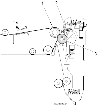
No. Description No. Description 1 ITB drive roller 3 Paper transfer roller 2 Discharge plate IMAGE TRANSFER UNIT MECHANISM
Drive Mechanism
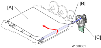
The image transfer belt is driven by the "PCU motor: Black/ ITB drive motor" via the gear and the ITB drive roller.
[A]: Image transfer belt : ITB drive roller
[C]: PCU motor: Black/ ITB drive motor
Transfer Bias
The bias to the Image transfer belt is applied to the image transfer roller of each color from the transfer power pack.

[A]: Image transfer belt : Image transfer roller
The 5 springs, in order from the right (double-side unit), consist of "C (cyan), secondary transfer, BK (black), Y (yellow) and M (magenta)" transfer bias terminals.
Detailed Descriptions
ITB Contact and Release
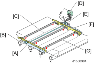
To prevent early deterioration of the color photosensitive drum, the Image transfer belt unit is provided with a contact/separation mechanism and, during monochrome printing, separation of the image transfer belt from the color photosensitive drum is controlled. Contact/separation of the image transfer belt unit is performed via a gear from an ITB contact and release motor (also used as a magenta toner supply motor). Separation or contact is detected by the ITB contact and release sensor.
[A]: Slider : Drum
[C]: Contact and release cam
[D]: ITB contact and release motor (also used as a magenta toner supply motor) [E]: ITB contact and release sensor
[F]: Guide
[G]: Image transfer roller
Image Transfer Belt Drive Control
FG Control is performed (Frequency Generator control: ensures precision of motor operation)
Image Transfer Flow
By arranging the imaging sequence in the order Y > M > C > Bk, cyan is laid on top of magenta, which increases tolerance to image blurring and image reddening when dark blue is output, and improves image quality.
[*]IMAGE TRANSFER BELT CLEANING MECHANISM
Image transfer cleaning is performed by a cleaning blade (counter method).
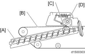
Due to downsizing of machine width, the cleaning unit is installed on top of the image transfer unit. Therefore, to replace the cleaning unit, replacement must be performed after taking out the Image transfer unit and inverting it.
[A]: Toner collection coil : Image transfer belt
[C]: Image transfer cleaning blade [D]: Toner collection coil
[*]PAPER TRANSFER UNIT MECHANISM
Paper Transfer Mechanism
A bias is applied to the ITB drive roller to transfer the image on the image transfer belt to the paper (repulsion transfer). As there is no paper between the image transfer roller and toner image, this method is not easily affected by paper conditioning.
Also, toner adsorption on the paper is facilitated by the static charge eliminator of the paper transfer unit (no charge is applied).
PTR (Paper Transfer Roller) Drive
The rotation of the paper transfer roller follows that of the ITB drive roller.
PTR (Paper Transfer Roller) Contact and Separation
If the paper transfer roller is permanently in contact with the image transfer belt, toner on the Image transfer belt moves to the roller and soils the underside of the paper surface, therefore the Paper transfer roller is separated during process control or MUSIC control (it is not separated during real-time process control).
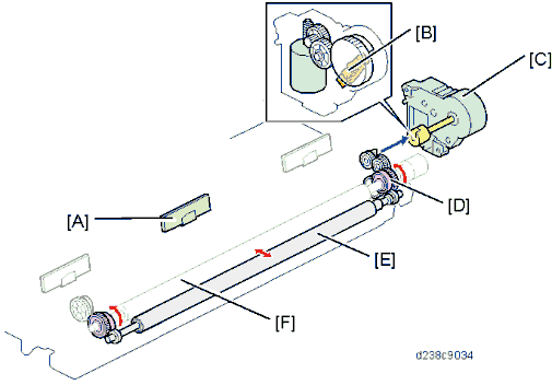
Separation of the paper transfer roller is achieved by transmitting the drive of the paper transfer contact motor via the ITB unit joint.
Detailed Descriptions
[A]: TM/ID sensor (center)
: Paper transfer roller HP sensor
[C]: Paper transfer contact and release motor [D]: Cam
[E]: Paper transfer roller [F]: ITB drive roller
Separation
To achieve paper separation, a curvature separation method which separates the paper transfer roller and Image transfer belt is employed.
TM/ID Sensor
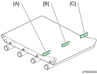
[A]: TM/ID sensor (front) : TM/ID sensor (center) [C]: TM/ID sensor (rear)
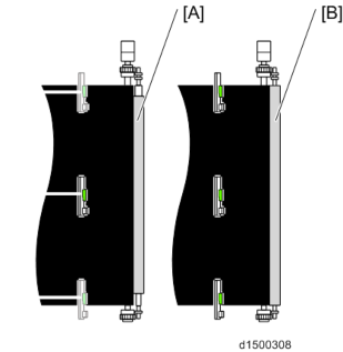
[A]: Paper transfer roller (standard roller)
: Paper transfer roller (Imageable Area Extension Unit Type M19)
When Imageable Area Extension Unit (316mm) is equipped, 316mm width printing is done instead of Real Time Process Control at margin.
Detailed Descriptions
[*]1st tray settings:PAPER FEED/ TRANSPORT SECTION
OVERVIEW
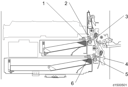
No. Description No. Description 1 Pick-up roller (1st paper tray) 4 Paper feed roller (2nd paper tray) 2 Paper feed roller (1st paper tray) 5 Friction roller (2nd paper tray) 3 Friction roller (1st paper tray) 6 Pick-up roller (2nd paper tray)
In this machine, an RF paper feed system is employed, and the paper feed roller, friction roller and pick-up roller are high durability rollers.PAPER FEED/ TRANSPORT PART
The paper feed tray consists of 2 units, i.e., a main double tray and a bypass feed tray. By using the 1st tray as a fixed tray, and the 2nd tray as a universal tray, a space-saving two-step feed is enabled.
Tray
Paper sizeLoading number of sheets Corresponding paper thickness
1st paper trayA4 landscape - A5 landscape
550 sheets
60 to 300 g/m22nd paper tray SRA3 - postcard 550 sheets 60 to 300 g/m2 Bypass feed tray SRA3 - postcard 100 sheets 60 to 300 g/m2 Duplex unit SRA3 - A6 portrait Interleave 60 to 169 g/m2
Tray Base Plate Lift
When the paper feed tray is set in the machine, the set switch at the rear of the tray switches ON, and it is detected that the tray is set.
The coupling between the shaft at the rear of the tray and the lift motor then engages, the motor rotates, and the tray base plate is lifted. The tray base plate lifts until the paper surface pushes the pick-up roller up, the upper limit sensor switches OFF (interrupt), and the machine enters paper feed standby mode.
When the tray is removed, the coupling is released, and the base plate moves down. The lift motor then rotates until the coupling returns to the home position.
Detailed Descriptions
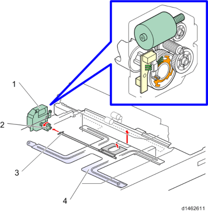
No. Description No. Description 1 Lift motor 3 Tray rear shaft 2 Coupling 4 Tray bottom plate
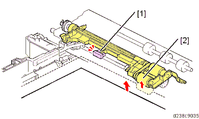
No. Description No. Description 1 Upper limit sensor 2 Pick-up roller
Detailed Descriptions
Paper Feed Mechanism
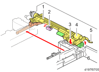
No. Description No. Description 1 Pick-up arm 4 Paper feed roller 2 Upper limit sensor 5 Feed guide 3 Pick-up roller 6 Friction roller
The paper feed unit employs an RF system.
In a conventional FRR system, transport of 2 sheets at a time is prevented by reverse rotation of the separating roller, but in the RF system, paper separation is assisted by the resistance of a separating roller with a torque limiter (reverse drive is not performed).
When the paper feed tray is set in the machine, the pressure release lever is pressed, the Friction roller comes in contact with the paper feed roller, and the pick-up roller contacts the top of the paper (to prevent paper remaining, when the paper feed tray is withdrawn, the arm returns and contact with the rollers is released).
The machine enters paper supply standby mode when the tray bottom plate moves up. When the paper feed motor is switched ON, the rollers rotate and paper is supplied.
The roller holder functions as a paper guide and roller clip ring. The roller holder prevents the paper from winding up.
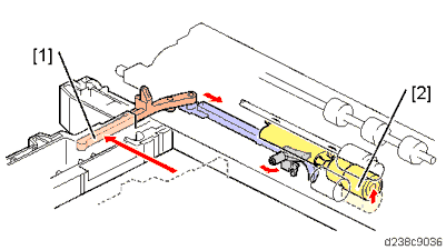
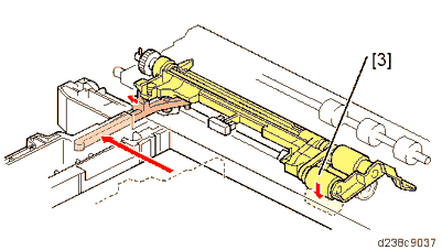
No. Description No. Description 1 Pressure release lever 3 Pick-up roller 2 Friction roller
Detailed Descriptions
Paper Feed Transport Mechanism
In this machine, to maintain the paper gap constant, switching the paper feed roller ON/OFF adjusts the paper feed timing.The paper feed motor is switched ON, and the first sheet is supplied.
Just before the rear edge of the first sheet leaves the paper feed roller, the paper feed motor switches OFF.
When the first sheet is fed a predetermined distance by the downstream transport roller, the paper feed motor switches ON to supply the second sheet of paper.
Paper Size Detection (1st Paper Supply Tray)
Size cannot be detected only with set detection.
A4 LEF, LT LEF, B5 LEF, and A5 LEF (select with UP mode, default is A4 LEF)
Paper Size Detection (2nd Paper Supply Tray)
The end fence interlocking rotation detection plate is an automatic detection system which recognizes patterns by a 4-position push switch.Size is detected by the detection patterns of knobs 1, 2, 3, and 4. Tray set is detected by another switch.
If there has been a change in the pattern, "MFP tray automatic size detection" control is performed continuously.
If the paper size is selected manually by user setting, the automatic size detection is overridden.

| No. | Description | No. | Description |
| 1 | End fence | 3 | Size detection actuator |
| 2 | Paper size switch | 4 | Tray set switch |
2nd tray detection sizes:
SRA3, A3, B4, A4 SEF, LT SEF, B5 SEF, A4 LEF, B5 LEF, and A5 LEF2nd tray size detection patterns:
Size | Knob | |||
| 4 | 3 | 2 | 1 | |
| SRA3(12"×18") | 1 | 0 | 1 | 0 |
| A3(DLT) | 0 | 1 | 0 | 0 |
B4(LG) | 0 | 0 | 1 | 1 |
| 0 | 1 | 1 | 1 | |
| A4 portrait | 1 | 1 | 1 | 0 |
| LT portrait | 1 | 1 | 0 | 0 |
| B5 portrait | 1 | 0 | 0 | 0 |
| A4 landscape(LT landscape) | 0 | 0 | 0 | 1 |
Size | Knob | |||
| 4 | 3 | 2 | 1 | |
| B5 landscape(Exe landscape) | 0 | 0 | 1 | 0 |
| A5 landscape | 0 | 1 | 0 | 1 |
Detailed Descriptions
- "0" is switch ON (PUSH), "1" is switch OFF.
- The figures in parentheses are automatic paper size switch can be switched over in SP mode (for SP settings, see "SP mode (paper supply transport)": SP5-181-002 to 006).
* SRA3=320×450mm(12.6"×17.7")
* Exe LEF=10.5"×7.25" - If a pattern other than the above is detected, a blank is displayed on the control panel.
Remaining Paper Detection
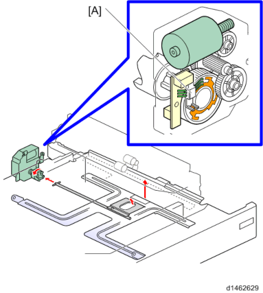
When the lift motor rotates, the remaining paper sensors 1, 2 [A] built into the motor switch ON (unblocked) or OFF (blocked). Paper remaining in the paper feed tray is detected by the combination of ON/OFF for the two sensors.
There are the following 4 remaining paper detection levels:
| Remaining paper status | 100% | 70% | 30% | 10% |
| Remaining paper status sensor 1 | ON | OFF | OFF | ON |
| Remaining paper status sensor 2 | ON | ON | OFF | OFF |
| Control panel remaining paper display | Bar 4 | Bar 3 | Bar 2 | Bar 1 |
Paper End Detection
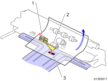
When there is no more paper in the paper feed tray, the leading edge of the paper end feeler falls into a notch in the base plate, and the paper end sensor at the rear edge of the end filler switches ON (pass).
| No. | Description | No. | Description |
| 1 | Paper end sensor | 3 | Notch |
| 2 | End feeler |
Detailed Descriptions
Paper Supply Drive
The 1st/2nd pick-up rollers and 1st/2nd paper feed rollers are driven by the paper feed motor. The 1st/2nd separation rollers are driven by the transport motor.The bypass transport roller is driven by the bypass/duplex motor, and the registration roller is driven by the registration motor.

| No. | Description | No. | Description |
| 1 | Paper feed motor | 6 | Bypass transport roller |
| 2 | Transport motor | 7 | Transport roller (2nd tray) |
| 3 | Pick-up roller (1st tray) | 8 | Paper feed roller (2nd tray) |
| 4 | Paper feed roller (1st tray) | 9 | Pick-up roller (2nd tray) |
| 5 | Transport roller (1st tray) |

| No. | Description | No. | Description |
| 1 | Registration roller (Driven) | 3 | Registration motor |
| 2 | Registration roller (Drive) |
Detailed Descriptions
Paper Dust Removal Mechanism
The registration mechanism removes paper scraps using the paper removal Mylar in contact with the driven roller (resin). Paper scraps removed by the paper removal Mylar are collected in the paper dust container.
| No. | Description | No. | Description |
| 1 | Paper dust container | 3 | Registration roller (Driven) |
| 2 | Paper dust removal Mylar | 4 | Registration roller (Drive) |
BYPASS FEED SECTION
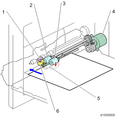
No. Description No. Description 1 Manual feed lever end sensor 4 Bypass/Duplex motor 2 Bypass paper feed roller 5 Bypass/Reverse roller 3 Bypass pick-up roller 6 Paper detection filler
Bypass Feed Paper/ Separation Mechanism
The bypass paper feed mechanism employs an FRR system. The bypass paper feed unit comprises a paper feed roller, reverse roller and pick-up roller.
When the paper feed tray is selected and the machine is started, the bypass pick-up solenoid is switched OFF, and paper is supplied by the bypass/duplex motor (CCW).
In standby mode, the bypass pick-up roller is not in contact with the paper surface. This is opposite to the paper feed tray.
Detailed Descriptions
Bypass Feed Paper Size Detection
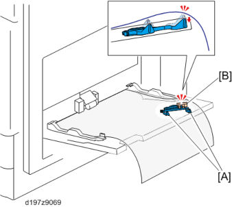
Paper size width detection is performed by the bypass width sensor (rotary switch).
The bypass feed size switch has a rotation plate which rotates together with the side fence of the bypass feed table, and detects the paper size.
Paper portrait/landscape is determined by the length sensor.
Two feelers [A] for the bypass length sensor are added to the rear of the tray to prevent false detection of paper length caused by floating at the rear of paper when long paper is set without pulling out the bypass tray extension.
Bypass Feed Paper End Detection
To detect bypass feed paper end, a paper detection feeler and bypass feed paper end sensor are provided.
When the paper is set, the bypass feed paper end sensor switches ON (interrupt), and paper set is detected.
When there is no more paper, the detection feeler falls into a hole in the bypass feed table, the bypass feed paper end sensor switches OFF (pass), and paper end is detected.
Bypass Paper Feeder Drive
The paper feed roller, Reverse roller and pick-up roller are driven by the bypass/duplex motor.
[*]DUPLEX SECTION

| No. | Description | No. | Description |
| 1 | Reverse sensor | 6 | Duplex exit roller |
| 2 | Duplex entrance roller 1 | 7 | Duplex exit sensor |
| 3 | Duplex entrance sensor | 8 | Registration roller |
| 4 | Duplex entrance roller 2 | 9 | Paper exit junction gate |
| 5 | Duplex transport roller | 10 | Reverse roller |
