Transport Inversion Mechanism
The paper passes through the junction gate, and is fed to the duplex unit past reverse rotation sensor and reverse rotation roller.

Duplex Drive
The rollers are driven by the following motors:
Interleave Mechanism
The duplex unit, in order to reduce the overall duplex copying time, performs interleaving.
Paper exit from main machine
1-bin tray exit from main machine
This SP is used to check the operation of the sensor. It confirms that the sensor can be switched off and on normally. (Default: On). This check can be used regardless of the User Tool setting.
Even if the sensor is switched off with the User Tool setting, a check can be done with this SP code.
Conditions for Detection of the PDL 5-1
PDL Detection by the Printer System, PCL Interpreter and PS Interpreter 5-1
PDL Selection and Switching 5-2
Triggers 5-3
SM Appendix iii D243/D244
The paper passes through the junction gate, and is fed to the duplex unit past reverse rotation sensor and reverse rotation roller.

| No. | Description | No. | Description |
| 1 | Fusing exit sensor | 4 | Paper exit junction gate |
| 2 | Reverse sensor | 5 | Duplex entrance roller 1 |
| 3 | Reverse roller |
Duplex Drive
The rollers are driven by the following motors:
| Rollers | Drive sources |
| Reverse roller | Reverse motor |
| Duplex entrance roller 1 | Duplex entrance motor |
| Duplex entrance roller 2 | Duplex entrance motor |
| Duplex transport roller | Bypass/ Duplex motor |
| Duplex exit roller | Bypass/ Duplex motor |
The duplex unit, in order to reduce the overall duplex copying time, performs interleaving.
Paper exit from main machine
| Length | No. of interleaves |
| Less than 216 mm | 3 |
| 216-432 mm | 2 |
| 432-457.2 mm | 1 |
1-bin tray exit from main machine
| Length | No. of interleaves |
| Less than 216 mm | 2 |
| 216-432 mm | 1 |
- 3 sheet interleave
1 sheet undersurface -> 2 sheet undersurface -> 3 sheet undersurface -> 1 sheet top surface
-> 4 sheet undersurface -> 2 sheet top surface - 2 sheet interleave
1 sheet undersurface -> 2 sheet undersurface -> 1 sheet top surface -> 3 sheet undersurface
-> 2 sheet top surface -> 4 sheet undersurface
3-sheet interleaving

Detailed Descriptions
PAPER EXIT UNIT

No. Description No. Description 1 Reverse sensor 5 Duplex entrance sensor 2 Reverse roller 6 Paper exit sensor 3 Paper exit junction gate 7 Paper exit roller 4 Duplex entrance roller 1
Delivery Location Change-over
The paper fed from the fusing unit is changed over by the junction gate in the "Paper exit/bridge unit" direction or the "duplex unit/1-bin tray" direction.
Machine paper exit/bridge unit direction- The registration sensor switches ON.
- The paper exit/pressure release motor switches ON (CCW).
- When the rear edge of the paper leaves the paper exit roller, the paper exit/pressure release motor switches OFF.

No. Description 1 Paper exit roller 2 Paper exit sensor 3 Paper exit junction gate
Duplex unit/1-bin tray direction- Registration sensor switches ON.
- The reverse motor switches ON (CCW).
- Before the leading edge of the paper reaches the paper exit junction gate, the junction gate moves to the duplex unit/1-bin tray direction.
* If the gate is in the duplex unit/1-bin tray direction, the gate is not changed over. - Before reversing the paper, the paper exit solenoid switches OFF.
- When the rear edge of the paper leaves the reverse roller, the reverse motor switches OFF.

No. Description 1 Reverse sensor 2 Reverse roller 3 Paper exit junction gate
Detailed Descriptions
Paper Exit Full/ Paper Exit Jam Detection
Paper exit full detection
This machine has no paper exit full sensor.
Paper exit jam detection
Paper exit jam is detected by the paper exit sensor.
DRIVE/SENSOR LAYOUT

Transport Roller Drive Source
Output Drive source Pick-up roller 1
Paper feed motorPaper feed roller 1 Pick-up roller 2 Detailed DescriptionsOutput Drive source Paper feed roller 2 Transport roller 1
Transport motorTransport roller 2 Registration roller Registration motor Paper exit roller Paper exit/ Pressure release motor Reverse roller Reverse motor Duplex entrance roller 1
Duplex entrance motorDuplex entrance roller 2 Duplex transport roller
Bypass/Duplex motorDuplex exit roller Bypass feed transport roller Bypass pick-up roller Bypass paper feed roller Bypass reverse roller ITB drive roller (belt) ITB drive motor
Paper transfer rollerITB drive roller (Follows rotation of image transfer belt) Fusing drive roller Fusing motor
Gate/Pick-up Arm Drive Source
Output Drive source Default position Application
1st tray pick-up roller
Paper feed motor
Pressure contact when OFFLoaded paper contact and release change-over
2nd tray pick-up roller
Paper feed motor
Pressure contact when OFFLoaded paper contact and release change-over
Paper exit junction gate
Paper exit solenoid
Paper exit path open when OFFPaper exit/ bridge unit or 1-bin/duplex path change-over
Bypass pick-up roller
Bypass pick-up solenoid
Clearance when OFFLoaded paper contact and release change-over
Detailed Descriptions
Inter-Roller Transport Path
Distance units: mm
Sensor PositionMd. From To Distance
1st tray paper feedPick-up roller 1 Paper feed roller 1 30.0 Paper feed roller 1 Transport roller 1 43.0
2nd tray paper feedPick-up roller 2 Paper feed roller 2 30.0 Paper feed roller 2 Transport roller 2 43.0 Transport roller 2 Transport roller 1 96.9
RegistrationTransport roller 1 Registration roller 86.8
Registration rollerPaper transfer roller (image transfer position)
95.5
FusingPaper transfer roller (nip) Fusing roller (nip) 85.0 Fusing roller (nip) Fusing exit roller 55.7 Paper exit Fusing roller (nip) Paper exit roller 143.6
Two-way distributionFusing roller (nip) Reverse roller 143.6 Reverse roller Duplex entrance roller 1 131.3
Duplex re-supplyDuplex entrance roller 1 Duplex entrance roller 2 120.4 Duplex entrance roller 2 Duplex transport roller 90.9 Duplex transport roller Duplex exit roller 110.2 Duplex exit roller Registration roller 94.7
Bypass feedBypass pick-up roller Bypass paper feed roller 30.0 Bypass paper feed roller Bypass transport roller 24.5 Bypass transport roller First transport roller 56.0
Distance units: mm
Md. From To Distance 1st tray paper feed
Transport roller 1
Transport sensor 1
16.8
2nd tray paper feedTransport roller 2 Transport sensor 2 24.3 Transport sensor 2 Transport sensor 1 88.7 Registration Registration sensor Registration roller 17.2 Paper exit Paper exit sensor Paper exit roller 17.0 Two-way distribution
Reverse roller
Reverse sensor
14.0
DuplexDuplex entrance roller Duplex entrance sensor 25.0 Duplex exit roller Duplex exit sensor 15.0 1-bin Reverse sensor 1-bin paper exit roller -
Paper Exit Driven Roller and Paper Support Guide
Paper Exit Driven Roller
The standard paper exit driven roller is drum-shaped and improves the stacking performance of the main machine exit tray by adding stiffness to the paper. However, if the paper has too much stiffness, it may jam as it enters the optional paper path when the internal peripheral is connected. Therefore, a flat type driven roller [A] is used to reduce the stiffness when transporting the paper.
The following options use the flat type driven roller:
- Internal Finisher SR3130
- Bridge Unit BU3070
- Internal Finisher SR3180
- Side Tray Type M3

Detailed Descriptions
Paper Support Guide
To prevent paper jam when the paper is delivered from the machine’s paper exit to the internal exit peripherals, attach the paper support guide [C] (supplied with the peripherals).

Removing Wrinkling in the Tray
When paper larger than A3 is set, wrinkles may appear at the end of the paper. As a countermeasure, the previous machine used an L-shaped sheet metal .

In this machine, the support components [A] and a decal are attached, which are also available to the end-user.


For small size paper, the side fences are sufficient because the paper is light, but paper larger than A3 must be set at the position indicated by the decal.
Tray 2, Paper Feed Unit PB3220/PB3210 (D787), and Paper Feed Unit PB3150 (D694) are also changed from L-shaped sheet metal to support component.
Factory Default:
[*]Tray 2: A3 (11 inches for NA only)
[*]Optional Paper Tray: A3 for all regions
Detailed Descriptions
FUSING
OVERVIEW
This machine employs a QSU fusing system wherein a lamp emits light to heat a sleeve belt.
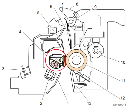
No. Description No. Description 1 Fusing sleeve thermostats 8 Fusing junction gate 2 Non-contact thermistor 9 Fusing exit roller (drive) 3 Thermopile 10 Pressure roller drive cam 4 Fusing sleeve belt 11 Pressure roller
5
Stripper Plate
12Pressure roller thermistors: Center, Edge, and Full-bleed edge 6 Fusing exit guide plate 13 Fusing entrance guide plate 7 Fusing exit roller (driven) 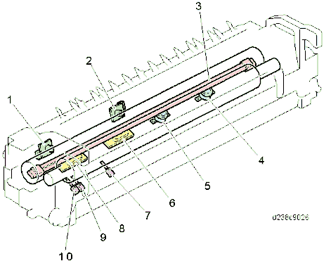
No. Description No. Description 1 Thermopile (edge) 6 Non-contact thermistor (center) 2 Thermopile (center) 7 Pressure roller thermistor (center) 3 Fusing lamp 8 Non-contact thermistor (edge) 4 Fusing sleeve thermostat (edge) 9 Pressure roller thermistor (edge)
5
Fusing sleeve thermostat (center)
10Pressure roller thermistor (Full-bleed edge)
Detailed Descriptions
MECHANISM
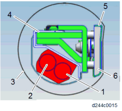
No. Description No. Description 1 Fusing lamp (center) 4 Reflector 2 Fusing lamp (edge) 5 Heat conduction plate 3 Fusing sleeve belt 6 Nip pad
- SU (Enhanced-Quick Start Up) fusing
This fusing unit has the heat conduction plate added to the pressure pad on the fusing nip and removed the shield plate control.
The model of 35 cpm or below require little amount of heat, so it controls the temperature by the heat conduction plate and lamp control at the edges and center.
The heat conduction plate on the nip (on the surface of the pressure pad) disperses the temperature deviation between the front and rear parts of the fusing sleeve belt, so as to even out the temperature.
A fusing sleeve belt is driven by drag rotation following a pressure roller, and presses a nip pad against the pressure roller to fix toner on the paper.
The fusing lamp heats the fusing sleeve belt, and the area of the belt which is heated moves in an anticlockwise direction so that heat is transmitted up to the contact point with the pressure roller.
Lamps
There are two lamps. Lamp power:
NA/TWN EU/AA/CHN Center 647 W 700 W Edge 344 W 527 W
Nip pad
Presses against the pressure roller to form a fusing nip. The top surface is covered with a slippery sheet.
Reflector
Transmits heat efficiently to the fusing sleeve belt.
Flanges
Situated on both ends of the fusing sleeve belt. They maintain the shape of the belt.
Heat conduction plate
Disperses the temperature deviation between the front and rear edges of the fusing sleeve belt to make the temperature uniform.
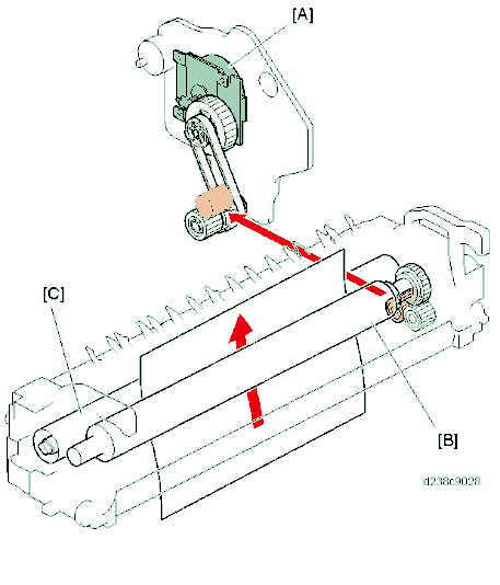
Fusing Drive
The pressure roller is driven by the fusing motor [A].
The fusing sleeve belt [C] is driven by the pressure roller (drag rotation).
Detailed Descriptions
Pressure Release Mechanism
The pressure release mechanism helps the user to remove paper jams from the fusing unit more easily. A pressure lever [C] is released by the drive of the paper exit/pressure release motor [A], and the pressure roller [D] separates from the fusing sleeve belt.
The pressure roller HP sensor [E] detects the encoder , and determines the position of the pressure roller.
After replacing the pressure roller, if the sensor does not detect the encoder for 3 times continuously after a job is completed, SC569-00 (Paper Exit/ Pressure Release Motor Error Detection) is generated.

Fusing Temperature Control
Warm-up mode
After power ON, fusing warm-up begins. The fusing motor is switched ON, the halogen lamp is energized, and the fusing temperature is increased to the "reload target temperature." When fusing warm-up is completed, the fusing motor stays ON for a certain time, and the fusing temperature is maintained at the "reload target temperature."
Standby mode
After fusing reload, when a certain time has elapsed, power supply to the halogen lamp is switched OFF, and the fusing motor is switched OFF. At the same time, the temperature is maintained at the "standby target temperature (SP1-107-001)" by the halogen lamp.
In standby mode, the Fusing motor rotates once every 60 minutes.
The operation interval of the Fusing motor can be changed by SP1-122-001 (Standby Rotation Setting Rotation Interval) but the change may cause the uneven glossiness on the image.
Printing ready mode
After returning to standby mode, the halogen lamp is re-energized, and the fusing temperature is raised to the "printing ready target temperature." If printing is not required, the machine again enters the standby mode after a certain time has elapsed.
If printing is required in standby mode during return, the halogen lamp is energized, the fusing temperature is increased to "target temperature after reload/after paper feed," and the print job starts.
CPM Down Control
Detailed Descriptions
To maintain image quality and machine quality, this machine has a low-temperature CPM mode and high-temperature CPM mode, and implements 3 levels of CPM down according to the usage situation and machine state.
Low-temperature CPM mode
In a low-temperature environment, the fusing lamp cannot keep up, and it may be difficult to maintain the fusing target temperature. To handle this, the detection temperature of the fusing center thermopile is checked every few seconds, and if the detection temperature during the check is below a threshold value, the CPM is decreased by 1 level.
This low temperature CPM reduction is performed in the following 3 levels:
CPM down level
Mode Level Normal CPM 100% CPM down 1 80% CPM down 2 65% CPM down 3 50%
Hot CPM mode
To shorten warm-up time and reduce the TEC value, this machine employs a fusing unit with a low heat capacity.
For this reason, the temperature of those parts of the fusing sleeve belt where paper does not pass easily increases, and the outside of the paper width may get extremely hot. In order to prevent the belt breakage due to this excessive temperature rise, CPM down is implemented depending on the usage conditions. CPM down can be implemented in the following 3 levels depending on the detection temperature of the temperature sensor, or the paper passage time.
- The down level % is a value for the case where a typical paper (Normal paper: A4 or smaller paper sizes) passes through the SEF at normal speed. There may be some differences depending on paper size/paper thickness.
CPM down level
- SU (Enhanced-Quick Start Up) fusing
Mode Level Normal CPM 100% CPM down 1 80% CPM down 2 50% CPM down 3 30%
CPM down determination using a temperature sensor
The temperature sensor is checked at given intervals, and if the detection temperature is above a threshold value, the CPM is decreased by 1 level.
Since the points at which temperature tends to increase depend on the paper size, the sensor used is changed depending on the paper size.
Paper width (length) Check sensor A3/DLT/B4 Pressure roller thermistor (edge) LT/A4 Thermopile (edge) B5/A5/B6/A6 Pressure roller thermistor (center)
CPM down determination using paper passage time
Depending on the paper size, it may not be possible to determine the points on the fusing sleeve belt which tend to rise in temperature by a sensor.
Therefore, time conditions are also used to determine CPM down, and if continuous paper passage time is above a threshold value, CPM is decreased by 1 level.
(When CPM down is performed by time conditions, CPM does not increase thereafter.)
Detailed Descriptions
Curl Correction Mechanism
This machine provides a curl reduction mechanism on the fusing exit.

Curling is reduced by bending in the reverse direction of the curl created at the fuser nip and forcibly adding resilience using the fusing exit roller , fuser exit driven roller [C], and fusing junction gate [A], located at the fuser nip exit.
The fusing junction gate is retracted for duplex printing/thick paper to prevent image smearing.

Drive
The fusing junction gate [C] is rotated via the arm by turning ON the fusing exit drive solenoid [A] located on the main machine side.
When the solenoid is ON, the fusing junction gate is at no curl correction position.

When the solenoid is OFF, it is put in the continuous curl correction position by spring [A].

Availability of curl correction by print mode
For duplex printing, or using thick paper, the fusing junction gate is retracted to prevent image smearing.
: Curl corrected (one-side printing only)
-: Curl not corrected
Thin PaperPlain Paper 1 Plain Paper 2
Middle ThickThick Paper 1 Thick Paper 2 Thick Paper 3 Thick Paper 4 Normal Paper


- - - - - Recycled Paper


- - - - - Color Paper


- - - - - Special Paper 1


- - - - - Special Paper 2


- - - - - Special Paper 3


- - - - - Letterhead


- - - - - Detailed Descriptions
Thin PaperPlain Paper 1 Plain Paper 2
Middle ThickThick Paper 1 Thick Paper 2 Thick Paper 3 Thick Paper 4 Preprinted Paper


- - - - - Bond Paper


- - - - - Cardstock


- - - - - OHP
(Transparency)- - - - - - - - Label Paper


- - - - - Coated: Matte - - - - - - - - Envelope - - - - - - - - Coated: Glossy - - - - - - - -
SP1-907-096 (Operation Setting: Fusing Exit SOL Setting)
By changing SP1-907-096, the curl correction mechanism can be enabled regardless of the paper setting.
If the fusing exit drive solenoid is ON, the curl correction function is OFF. If the fusing exit drive solenoid is OFF, the curl correction function is ON.
SP valueCurl Correction Tray Bypass 0 Normal Operation 1 Normal Operation Always OFF 2 Always OFF Normal Operation 3 Always OFF Always OFF 4 Normal Operation Always ON 5 Always ON Normal Operation 6 Always ON Always ON
For duplex printing, or printing to 1-bin tray, always no curl correction regardless of the SP setting, because the fusing junction gate would interfere with the transfer path.
Detailed Descriptions
ELECTRICAL PARTS
BLOCK DIAGRAM
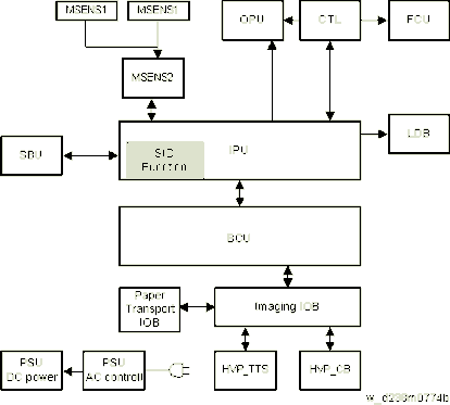
BOARD OUTLINE
Controller
Controls the MFP system overall. Comprises an x86CPU, controller ASIC, IO control ASIC, and RAM.
SBU
Scanning control circuit which performs analog signal processing and AD image conversion of the CCD scanned image.
It also has an IPU I/F, and controls scanner input output signals according to CPU commands.
LDB
LD control circuit which drives the laser diode with a universal driver.
BCU
Controls the engine.
IPU
Processes digital signals.
The SIO functions are included in the IPU for this machine. Thus the SIO board is removed.
SIO Function
Circuit which controls generation of SBU power, scanner internal sensor I/F, carriage drive stepping motor and LED drive.
MSENS1 (Proximity Sensor (Human Detection Sensor), MSENS2 (Proximity Sensor (Human Detection Sensor) Board)
Proximity sensors (human detection sensors) and proximity sensor (human detection sensor) board are equipped.
People are detected by IR sensors which sense the temperature difference between the human body and the temperature of the machine location.
IOB
Controls the MFP engine sensor, motor and solenoid.
FCU
Controls the fax program.
OPU
Controls the control panel.
HVP (Composite High-Voltage Power Supply TTS/CB)
Generates the high-voltage power required for process control. Divided into two units, i.e., transfer (TTS) and electrostatic/developing (CB).
PSU
Generates DC power from a commercial AC power supply, and supplies it to each control circuit. Comprises an A/C drive circuit for controlling the fixing heater.
Detailed Descriptions
ANTI-CONDENSATION HEATER FOR SCANNER, PCDU, AND PAPER FEED TRAY
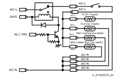
The power circuit of the anti-condensation heaters for scanner and PCDU is linked to the switch of the paper feed tray heater. Therefore, when the paper feed tray heater power is turned OFF, all heaters are de-energized. In addition, the operation during printing is controlled so as not to exceed the maximum power.
The behavior of the heaters when the machine is in standby mode is controlled by SP5-805-001 (Anti-Condensation Heater OFF/ON).
Heater
SP5-805-001
Plug-inEnergy saving
Standby
PrintingOFF(0)
ON
ONOFF
OFF
ON(1)
ON- Scanner heater
- PCDU heater
- Main machine tray heater
- Optional paper feed tray heater
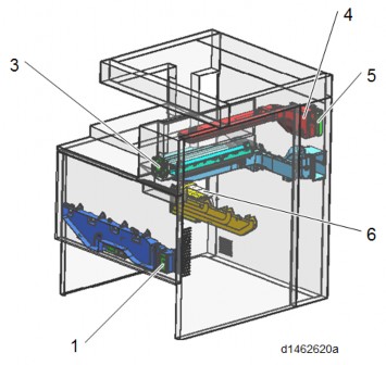
EXTERIOR COVER/ AIR FLOWS (FAN CONTROL)
OVERVIEW
Imaging system (front)
Imaging system (rear)
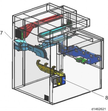
Electric system
Detailed Descriptions
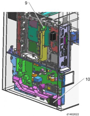
No. Part name 1 Development intake fan 3 Paper exit cooling fan 4 Fusing exhaust fan 5 Deodorization filter 6 Ozone exhaust fan 7 Toner supply cooling fan 8 Ozone filter/Dust filter 9 Controller box cooling fan 10 PSU cooling fan MECHANISM
By installing the duct corresponding to each fan, the air flow is efficiently controlled to a cooling target. Moreover, improvement in quietness and energy-saving efficiency is achieved by performing stepwise operation of the fan according to the imaging temperature.
Cooling of PSU
Air taken in by the PSU cooling fan is guided near the cooling target by the duct, and is efficiently cooled.
Cooling of Toner Supply Parts
Air taken in with the toner supply cooling fan is guided to circulate around the toner bottle, and is discharged from the side of the delivery tray to outside the machine. It is aimed to achieve heat insulation from the stack of paper to the toner bottle by reducing the melting point of the toner.
Cooling of PCDU parts
By discharging air taken in from the development intake fan at the front, from the ozone exhaust fan at the rear, a uniform air flow is attained and efficient cooling is realized. Discharge of ozone and scattering of toner are prevented by installing an ozone filter and a dust filter in front of the ozone exhaust fan.
Cooling of Fusing Parts
Air taken in from the paper discharge cooling fan at the front is discharged from the fusing heat discharge fan at the rear to outside the machine. By cooling the paper immediately after fusing, not only cooling of the fusing exit sensor but also reduction of stored heat of the stacked paper and reduction of curl are realized. This also serves to prevent condensation on the paper discharge guide sheet. As a measure against odor, a deodorization filter is installed downstream from the fusing exhaust fan.
Cooling in Controller Box
Air is circulated by the controller box cooling fan installed in the controller box, preventing temperature rise in the controller box.
Crisis Management When Temperature Rises in the Machine
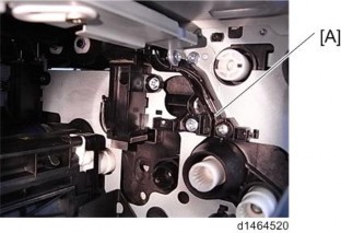
In order to suppress excessive temperature rise in the machine and maintain equipment quality, a temperature sensor (imaging temperature sensor (thermistor)) [A] is installed in the machine. The imaging temperature sensor (thermistor) detects the temperature environment in the machine, and controls cooling operation.
Detailed Descriptions
Overview of cooling operation in the machine
The temperature in the machine is detected during output and after output, and the interior of the machine is cooled by fan operation (stepwise operation of fan, prolonged fan rotation after paper has passed through) according to the temperature inside the machine.
However, if the temperature inside the machine rises significantly due to passing a large volume of paper, in addition to fan operation, the CPM is specified to control the temperature in the machine.
Cooling operation during output
Perform cooling operation under the following conditions.
Imaging temperatureLess than 34
34
35
36
37
38
40*1Fusing exhaust fan ON ON ON ON ON ON ON Ozone exhaust fan 20% 20% 30% 30% 40% 40% 40% Toner supply cooling fan - - - ON ON ON ON Development intake fan *3 - - - ON ON ON ON PSU cooling fan*2 ON ON ON ON ON ON ON
The operation start temperature can be modified by SP.- *1 If the imaging temperature reaches 41°C each fan will continue operating until it falls by 2°C.
- *2 Operating condition:
When the time interval from the previous job is less than 10 minutes. Or, when the time interval from the previous job is more than 10 minutes, and 5 minutes have elapsed from start of machine. - *3 Operating condition:
For 36°C or above, full speed rotation at 24V
Changes from low speed rotation to full speed rotation when printing continues for more than 5 minutes while the temperature inside the machine is 36°C or lower
Cooling operation after output
Usually, after output, fan operation is suspended.
If the temperature in the machine after output is high, fan rotation is continued after output to cool the interior of the machine.
Helmholtz Silencer
The Helmholtz silencer applies the resonance phenomenon called the "Helmholtz resonance" to emit a sound having reverse phase of the motor frequency by resonance and cancel the motor noise.
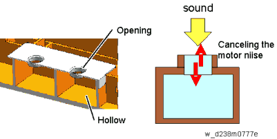
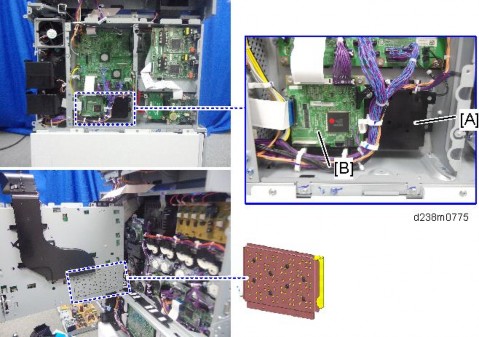
On this machine, it is located on the controller box side to reduce the noise. The BCU is mounted on the mold [A] of the Helmholtz silencer.
Detailed Descriptions
[*]At the start of the measurement period, read the values of SP8-941-001 to 005.ENERGY SAVE
ENERGY SAVER MODES
Customers should use energy saver modes properly, to save energy and protect the environment.
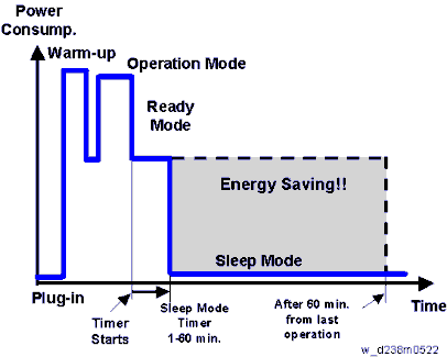
The area shaded grey in this diagram represents the amount of energy that is saved when the timers are at the default settings. If the timers are changed, then the energy saved will be different. For example, if the timers are all set to 60 min., the grey area will disappear, and no energy is saved before 60 min. expires.
Setting Items that are Related to Energy Saving
The user can set these timers with User Tools (Machine Features > System Settings > Timer Settings)
Sleep Mode Timer
User Tools (Machine Features > System Settings > Timer Settings)
After a specified period has passed, or [Energy Saver] is pressed, the machine enters Sleep mode in order to conserve energy. Specify the time to elapse before Sleep mode.
Default: [1 minute(s)]
Sleep mode timer may not work when error messages appear.
Depending on which embedded software architecture application is installed on it, the machine might take longer than indicated to enter Sleep mode.
Fusing Unit Off Mode (Energy Saving) On/Off
User Tools (Machine Features > System Settings > Timer Settings) Specifies whether Fusing Unit Off mode is enabled or not.
When Fusing Unit Off mode is enabled, the display is on but the fusing unit is off to save energy.
The machine requires roughly the same time as warm-up time to recover from Fusing Unit Off mode.
Default: [Off]
If [Fusing Unit Off Mode (Energy Saving) On/Off] is set to [On], you can specify when to exit Fusing Unit Off mode and the time to elapse before entering Fusing Unit Off mode.
If [Exit Fusing Unit Off Mode] is set to [On Printing], the machine exits Fusing Unit Off mode when printing is performed.
If [Exit Fusing Unit Off Mode] is set to [On Operating Control Panel], the machine exits Fusing Unit Off mode when a key other than the copy function key is pressed on the control panel of the machine.
If printing is performed with the copy function or a key in the copy function is pressed on the control panel of the machine, the machine exits Fusing Unit Off mode regardless of this setting. If the timer is set to [On], you can set the time from 10 seconds to 240 minutes, using the number keys.
Energy Saving Recvry. for Business Application.
User Tools (Machine Features > System settings > General Settings)
Specify whether or not to enable low-energy recovery from Sleep mode to use applications independent of the machine, such as Address Book Management or Browser.
Default: [Off]
If [On (Energy Saving)] is selected, it takes longer than usual to be ready to use the machine.
Detailed Descriptions
Recovery Time/ Reduced Electrical Consumption
Reduced electrical consumption in Sleep mode:
MP C2004 MP C2504 NA: 0.85 W
EU: 1.00 WNA: 0.85 W
EU: 1.00 W
Recovery time from Sleep mode
MP C2004 MP C2504 6.0 sec. 6.0 sec. POWER STATES OF THIS MACHINE
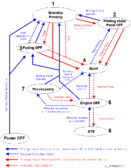
State Description 1
Standby/Printing2 Printing state/Panel OFF State when printing with the backlight of the operation panel turned off - State where normal operation is possible after warm-up
- State during printing
State Description 3 Fusing OFF State where the Standby Fusing OFF state is entered when the time set with the "Fusing Unit Off Mode (Energy Saving) On/Off" setting of the User Tools has elapsed. 4 Quiet state Quiet state is entered when the Energy Saving key is pressed or the time set with the "Sleep Mode Timer" of the User Tools has elapsed. This is a temporary energy saving state before entering sleep mode. 5 Engine OFF (Sleep mode) Entered from Quiet state with internal timer. 6 STR state (Sleep mode) Supplying of power and clock to the CPU and peripheral chips on the controller board is stopped. 7 Pre-recovery The Pre-recovery state is entered from STR state when the proximity sensor (human detection sensor) detects presence of a person.
This is the Energy Saving state where the power of the operation panel and HDD is ON and the power of the engine is OFF, but the backlight of the operation panel LCD is off.
- State where the operation panel is flashing and the fusing lamp is OFF.
- The bottom plate of the paper feed tray is raised.
- Basically, no homing (initialization) of peripheral devices is performed.
- The bottom plate of the paper feed tray is raised.
- The fusing lamp is turned OFF.
- The relevant power systems (24V, 12V, 5V) are turned OFF at the same time as the fusing lamp.
- When receiving a fax or printing is performed in engine OFF state, warm-up is started and printing is performed while the backlight of the operation panel is turned OFF.
Detailed Descriptions
Device state for each Energy Saving state
StateEnergy Saving LED Operation panel LCD Engine (Printer/Scanner)
HDD
CTLStandby/Printing ON ON ON ON ON
Printing state/Panel OFFON OFF ON
(Only scanner is in Quiet state)ON ON fusing OFF ON ON ON
(Both printer/scanner are in Quiet state)ON ON Quiet state ON OFF
ON*1ON
(Both printer/scanner are in Quiet state)ON ON Engine OFF Blinking gradually ON*1 Sleep
OFF or ON*1OFF OFF
ON*1ON STR state Blinking gradually Sleep OFF OFF STR Pre-recovery ON OFF
ON*1OFF ON ON
Detailed Descriptions
*1 When [Energy Saving Recvry. for Business Applicatn.] is [On (Energy Saving)], ON/OFF is determined by the internal timer of the Smart Operation Panel.
Transition of operation panel to Energy Saving when [Energy Saving Recvry. for Business Applicatn.] is [On (Energy Saving)]
Normally, the Energy Saving state of the operation panel LCD changes in step with the energy saving state of the MFP/LP main unit, but to support the scenario where an application that does not use the engine (printer/scanner) is executed from the operation panel, the Energy Saving state of the operation panel is transitioned through the three states ON, OFF, and Sleep with its internal timer when [Energy Saving Recvry. for Business Applicatn.] is [On (Energy Saving)].VERIFICATION OF UP TIME FOR EACH ENERGY SAVING STATE
The up time for each power state of the machine can be checked with SP8-961 (Electricity Status). It is also output on the SMC sheet.
SP Name Description SP8-961-001 Ctrl Standby Time Cumulative time of Engine OFF mode, Quiet mode, and Standby mode SP8-961-002 STR Time Cumulative time of STR mode SP8-961-003 Main Power Off Time Cumulative time of state in which the power plug is connected to the outlet but the main power is off SP8-961-004 Reading and Printing Time Cumulative time of state in which both the plotter engine and scanner engine are running or warming up SP8-961-005 Printing Time Cumulative time of the state in which the plotter engine is running SP8-961-006 Reading Time Cumulative time of the state in which the scanner engine is running SP8-961-007 Eng Waiting Time Cumulative time of state in which the power state of the engine is Standby state SP8-961-008 Low Power State Time Not used for this machine SP8-961-009 Quiet State Time Cumulative time of the state in which the power state of the engine is Quiet state SP8-961-010 Heater Off State Time Cumulative time of the state in which the power state of the engine is fusing OFF state SP8-961-011 LCD on Time Cumulative time of the state in which the backlight of the LCD is on.
Detailed Descriptions
CHECKING THE UP TIME BY DEVICE STATE
SP Name Description SP8-941-001 Operation Time Cumulative time of the state in which the engine state notification is enabled.
The state in which the engine is not running (such as when storing to HD only with the controller) is excluded from the running state.SP8-941-002 Standby Time Cumulative time of the state in which the engine state is not running. SP8-941-003 Low Power Time Not used for this machine SP8-941-004 Sleep mode time Cumulative time in Sleep Mode state. SP8-941-005 Off Mode Time Cumulative time in which the Energy Saving state of the device is engine OFF state. SP8-941-006
to 009Down time Cumulative time in which the device is disabled because itself or its component is in the following state. - SP8-941-006: SC (excluding mode SC)
- SP8-941-007: Jam (plotter)
- SP8-941-008: Jam (scanner)
- SP8-941-009: Supply/PM unit end
With this data, and the power consumption values from the specifications, we can estimate the amount of energy that is used by the machine.
This should only be used as a reference value, because the power consumption specifications are measured in a controlled environment with a constant power supply.
To get an exact measurement at the customer’s site, a watt meter must be used to measure the actual energy consumed.
To use SP8-941 to calculate the energy consumed:
[*]At the end of the measurement period, read the values of SP8-941-001 to 005 again.
[*]Find the amount of time spent in each mode (subtract the earlier measurement from the later measurement).
[*]Multiply this by the power consumption spec for each mode.
[*]Convert the result to kWh (kilowatt hours)
We recommend that the default settings related to energy saving should be kept.RECOMMENDATION
Detailed Descriptions
[*]First, the sensor detects the presence of the operator within the arc in front of the machine, and then signals the machine to leave the STR mode (or Engine OFF mode) and enter the Pre-recovery mode.PROXIMITY SENSOR (HUMAN DETECTION SENSOR)
OVERVIEW
The proximity sensor (human detection sensor) is located on the right upper corner of the main machine.
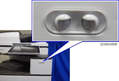
When the machine has been idle for a long period and the proximity sensor (human detection sensor) detects the presence of anyone in front of the machine, it signals the machine to prepare itself for quick recovery to operation status by shortening the time required for the machine to recover full operation (pre-recovery mode) before the operator even touches the machine or operation panel. The proximity sensor (human detection sensor) employs infrared and can detect the presence of the operator within an arc of 150° out to 1.8 m (6 ft.) away from the front of the machine.
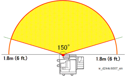
SENSOR OPERATION
There are three phases in the operation of the proximity sensor (human detection sensor):
[*]Second, as soon as the machine enters the Pre-recovery mode it resets the Engine Off mode timer for 5 min. If the operator does not touch the machine for 5 minutes, the machine slips back into the Engine Off mode. If the operator touches the LCD, or opens and closes the ADF or front cover, etc., the machine shifts to Standby mode.
[*]Third, once the machine enters Standby mode, if the operator does nothing to start operation, the machine will gradually step down from Standby mode to Lower Energy mode, Quiet mode, Engine Off mode, and then finally to STR mode.
[*]STR mode. Suspend-to-RAM mode. The power supply to the CPU, adjacent chips, and the clock on the controller board is shut down.OPERATION MODES
Here are more details about these operation mode levels.
[*]Engine Off mode. The fusing lamps and other engine components remain off. The operation panel backlight is off, but there is power supplied to the operation panel and the controller boards.
[*]Pre-recovery mode. The operation panel and HDD are on but the engine components remain off (Energy Save mode). However, the operation backlight still remains off, so there is no change on the operation panel to indicate that the machine has shifted from STR mode, through Engine Off mode, and into Pre-recovery mode.
[*]Quiet mode. Fusing lamps still remain off, but the HDD and SD cards are accessible so the machine can receive jobs (Data In) and incoming faxes.
[*]Lower Power mode. Finally, power is restored to the fusing lamps but maintained at low temperature.
[*]Standby mode. The machine is ready to operate.
Detailed Descriptions
[*]Cycling the machine off/on does not cancel this error.USER TOOL
The operation of the proximity sensor (human detection sensor) can be switched off and on with a User Tool setting.- Press "User Tools" on the operation panel.
- Select Machine features > System Settings > General Settings > Human Detection Sensor
- You can switch the sensor off/on by selected Disabled/Enabled. The default setting is "Enabled".
RELATED SC CODES
One of two SC codes is issued if the proximity sensor (human detection sensor) fails.
SC869-01 Proximity sensor (human detection sensor) failure: Error 1
The sensor remained on for over 24 hours.
[*]When this error occurs the machine enters sensor failure mode and ignores subsequent input from the proximity sensor (human detection sensor).
[*]Even though the sensor is on, the machine does not enter Pre-recovery mode, and the Engine Off timer setting is not affected and continues to operate normally.
[*]To cancel the error, switch off the proximity sensor (human detection sensor) with the User Tool setting described above.
[*]The sensor and its components require replacement.
SC869-02 Proximity sensor (human detection sensor) failure: Error 2
The sensor remained off, even after the operator performed 20 actions with the machine operation panel, opening and closing the front cover, ADF, etc. The machine will issue this error code after every 20 events in operation of the machine.
[*]Cycling the machine off/on does not cancel this error.
[*]To cancel the error, switch off the proximity sensor (human detection sensor) with the User Tool setting described above.
[*]The sensor and its components require replacement.
There is one proximity sensor (human detection sensor) related SP code: SP5102-203 Auto Detect: human detection check. This is an on/off check.RELATED SP CODE
[*]Enter "1" to switch the sensor on.
This SP is used to check the operation of the sensor. It confirms that the sensor can be switched off and on normally. (Default: On). This check can be used regardless of the User Tool setting.
Even if the sensor is switched off with the User Tool setting, a check can be done with this SP code.
D243/D244
SERVICE MANUAL APPENDICES
D243/D244 APPENDICES
TABLE OF CONTENTS
SPECIFICATIONS 1-1
- MACHINE SPECIFICATIONS 1-1
- GENERAL SPECIFICATIONS 1-1
- PRINTER SPECIFICATIONS 1-3
- SCAN SPECIFICATIONS 1-5
- OTHER SPECIFICATIONS 1-7
HDD Specifications 1-7
Speed Specifications 1-8
OFF/ Sleep Mode Shift Time 1-9
OFF/ Sleep mode Watts, Recovering Time 1-9
Noise (Sound Power Level) 1-10
- SOFTWARE ACCESSORIES 1-11
- PRINTER DRIVERS 1-11
- SCANNER AND LAN FAX DRIVERS 1-12
- SUPPORTED PAPER SIZES 1-13
- ORIGINAL SIZE DETECTION 1-13
- PAPER FEED 1-15
Tray 1 to 4 1-15
Bypass Tray 1-18 - PAPER EXIT 1-22
Main unit tray, 1 bin tray, Inner shit tray, Side tray 1-22
Internal Finisher SR3130 1-25
Booklet Finisher SR3220 1-29
Bridge Unit 1-37
- OPTION SPECIFICATIONS 1-41
- PAPER FEED UNIT PB3150 (D694) 1-41
1.4.2 PAPER FEED UNIT PB3220/PB3210 (D787) 1-41
1.4.3 ARDF DF3090 (D779-17, -21) 1-42
1.4.4 SPDF DF3100 (D3B0-17, -21) 1-43
1.4.7 1 BIN TRAY BN3110 (D3CQ) 1-46- SIDE TRAY TYPE M3 (D725) 1-44
- INTERNAL SHIFT TRAY SH3070 (D691) 1-45
1.4.8 BRIDGE UNIT BU3070 (D685) 1-46
- INTERNAL FINISHER SR3130 (D690) 1-47
Finisher part specifications 1-49
Stapler unit specifications 1-50 - PUNCH UNIT PU3040 NA/EU/SC (D716) 1-51
- INTERNAL FINISHER SR3180 (D766) 1-52
Finisher part specifications 1-53
Stapler unit specifications 1-54 - BOOKLET FINISHER SR3220 (D3B9) 1-55
- PUNCH UNIT PU3050 NA/EU/SC (D717) 1-58
- BANNER PAPER GUIDE TRAY TYPE M19 (D3BF) 1-59
- PAPER FEED UNIT PB3150 (D694) 1-41
- MACHINE SPECIFICATIONS 1-1
PREVENTIVE MAINTENANCE 2-1
- PREVENTIVE MAINTENANCE 2-1
- PREVENTIVE MAINTENANCE ITEMS 2-1
Mainframe 2-1
ARDF DF3090 2-5
SPDF DF3100 2-5
Paper Feed Unit PB3220/PB3210 2-6
1 Bin Tray BN3110 2-6
Bridge Unit BU3070 2-7
Internal Shift Tray SH3070 2-7
Side Tray Type M3 2-7
Booklet Finisher SR3220/Punch Unit PU3050 2-7
Internal Finisher SR3130 2-8
Internal Finisher SR3180 2-8
- PREVENTIVE MAINTENANCE ITEMS 2-1
- PREVENTIVE MAINTENANCE 2-1
ENGINE SP MODE TABLES 3-1
- ENGINE SP TABLES - SP1000-1 3-1
- SP1-XXX (FEED) 3-1
- SP1-XXX (FUSING) 3-6
- ENGINE SP TABLES - SP1000-2 3-82
- SP1-XXX (DRIVE, FAN) 3-82
- ENGINE SP TABLES - SP2000-1 3-100
3.3.1 SP2-XXX (DRUM) 3-100 - ENGINE SP TABLES - SP2000-2 3-173
3.4.1 SP2-XXX (DRUM) 3-173 - ENGINE SP TABLES - SP3000 3-254
- SP3-XXX (PROCESS) 3-254
- ENGINE SP TABLES - SP4000 3-304
D243/D244 ii SM Appendix- SP4-XXX (SCANNER) 3-304
- ENGINE SP TABLES - SP5000 3-331
3.7.1 SP5-XXX (MODE) 3-331 - ENGINE SP TABLES - SP6000 3-337
- SP6-XXX (PERIPHERALS) 3-337
- ENGINE SP TABLES - SP7000 3-352
- SP7-XXX (DATA LOG) 3-352
- INPUT AND OUTPUT CHECK 3-385
- INPUT CHECK TABLE 3-385
Main Machine, Paper Feed Tray 3-385
ADF 3-398
Finisher 3-401 - OUTPUT CHECK TABLE 3-412
Main Machine, Paper Feed Tray 3-412
ADF 3-423
Finisher 3-425
- INPUT CHECK TABLE 3-385
- TEST PATTERN PRINTING 3-432
- ENGINE SP TABLES - SP1000-1 3-1
CONTROLLER SP MODE TABLES 4-1
- CONTROLLER SP TABLES - SP5000 4-1
- SP5-XXX (MODE) 4-1
- CONTROLLER SP TABLES - SP7000 4-70
- SP7-XXX (DATA LOG) 4-70
- CONTROLLER SP TABLES - SP8000 4-96
- SP8-XXX (DATA LOG 2) 4-96
Keys and abbreviations in Data Log 2 4-97
- SP8-XXX (DATA LOG 2) 4-96
- PRINTER SERVICE MENU 4-153
- SP1-XXX (SERVICE MODE) 4-153
- SCANNER SERVICE MENU 4-168
- SP1-XXX (SYSTEM AND OTHERS) 4-168
- SP2-XXX (SCANNING-IMAGE QUALITY) 4-170
- CONTROLLER SP TABLES - SP5000 4-1
SOFTWARE CONFIGURATION 5-1
- PRINTING FEATURES 5-1
- AUTO PDL DETECTION FUNCTION 5-1
- PRINTING FEATURES 5-1
Conditions for Detection of the PDL 5-1
PDL Detection by the Printer System, PCL Interpreter and PS Interpreter 5-1
PDL Selection and Switching 5-2
Triggers 5-3
SM Appendix iii D243/D244
