Troubleshooting
Target Part/SP No.
- Execute SP2-111-004 (Forced Line Position: Adj. Mode d).
- Execute SP2-194-007 (MUSIC Execution Result: Execution Result).
Countermeasure (3): Image transfer belt/ Image transfer unit defective
- Execute SP2-112-001 (TM/ID Sensor Check Execute).
- Check SP2-112-010 (TM/ID Sensor Test General:FCR).
- Normal If the result is "111"
-->Execute other countermeasures. - Vsg adjustment is failed if the result is "2xx", "x2x", or "xx2"
-->Execute recovery operation for SC370 - There is a high probability that contaminants, scars, or irregularities may exist on the belt if the result is "3xx", "x3x", or "xx3"
-->Execute the following procedure;- Remove the image transfer unit, and check for abnormalities such as contaminants or scars, and set it after cleaning.
- Execute SP2-111-004 (Forced Line Position: Adj. Mode d).
- Execute SP2-194-007 (MUSIC Execution Result: Execution Result).
- If it fails, replace the image transfer belt/ Image transfer unit.
- There is a high probability that contaminants or curls may exist on the belt if the result is "5xx", "6xx", "7xx", "8xx", "x5x", "x6x", "x7x", "x8x", "xx5", "xx6", "xx7", or "xx8".
- Normal If the result is "111"
- Remove the Image Transfer Unit, and check for abnormalities such as contaminants or scars, and set it after cleaning.
- Execute SP2-111-004 (Forced Line Position: Adj. Mode d).
- Execute SP2-194-007 (MUSIC Execution Result: Execution Result).
- If it fails, replace the image transfer belt/ Image transfer unit.
Countermeasure (4): TM/ID sensor defective
Follow the next step if executing SP2-111-004 (Forced Line Position: Adj. Mode d) and SP2-194-007 (MUSIC Execution Result: Execution Result) fails.- Clean the TM/ID Sensor.
- Check the harness and connector for TM/ID sensor.
- Replace the TM/ID sensor.
- Replace the BCU.
Countermeasure (5): Paper transfer contact/release mechanism defective
Check if the MUSIC/ProCon Pattern is attached on the Paper Transfer Roller. If it is attached, separating may be defective.- Execute SP5-804-255 (OUTPUT Check: Paper Transfer Contact Operation) to operate the paper transfer contact and release motor to check the separating operation of the paper transfer roller.
- Check for a broken harness or connector disconnection.
- If the problem cannot be solved, replace the Imaging IOB.
Countermeasure (6): Laser optics positioning motor in laser unit error
- Check the operation of the laser optics positioning motor and check for a broken harness or connector disconnection. If an abnormality is detected, replace the Laser Unit.
- If the problem cannot be solved, replace the Imaging IOB.
WHEN SC370 (TM (ID) SENSOR CALIBRATION ERROR) IS DISPLAYED
Causes
- TM (ID) sensor connector missing/connection error
- TM (ID) sensor detection window dirt
- TM (ID) sensor malfunction
- Undulation in the ITB, or belt slippage
Solutions
Check if the SC occurs by turning the power OFF then ON. If the SC occurs again, do the following steps.- Check if all connectors related to TM/ID sensor are connected securely. Reconnect the connectors if they are disconnected, or loose.
- If TM/ID sensor is contaminated, clean it with dump cloth (never use a dry cloth or alcohol).
- Check if there is an abnormality on the image transfer belt surface.
- If any abnormalities are found on the image transfer belt surface, replace the image transfer belt.
- Belt scratched
- Belt corrugation, belt skew
- Cleaning failure
- Background stains
- Filming
- Check the TM/ID sensor for malfunctions, and recover or replace it if there are any defects.
- Check the harness. Replace the harness if it is disconnected, or damaged.
- If the SC is not cleared even after performing steps 1 to 6, replace the BCU
Recovery Check Procedure
- Execute Vsg adjustment with SP3-320-001(Vsg Adj: Execute
Sensor).
- Check the result with SP3-323-001(Vsg Adj OK?: Latest).
- If code is "1": Recovered
- If code is not "1": Not recovered
Adjustment after Recovery
After performing recovery on SC370, execute the following adjustment procedures.- Execute SP2-111-004 (Forced Line Position: Adj. Mode d).
- Execute the following SPs and check the results:
- SP2-194-007 (Execution Result)
- SP2-194-010 (Error Result: C)
- SP2-194-011 (Error Result: M)
- SP2-194-012 (Error Result: Y) Execute result sample Factory default: 0
Success: 1
- Execute SP3-011-001 (Manual ProCon :Exe).
- Execute the following SPs and check the results.
- SP3-012-001 to 010 (Front)
- SP3-012-011 to 020 (Center)
- SP3-012-021 to 030 (Rear)
Execute result sample (In order of YMCK from left)- Factory default:[00,00,00,00]
- Starting adjust:[99,99,99,99]
- Fail Vsg adjust(Y):[21,99,99,99]
- Error of Development gamma Max(C):[99,99,55,99]
- Succeed:[11,11,11,11]
WHEN SC501, SC502, SC503, OR SC504 (PAPER TRAY ERROR) IS DISPLAYED
SC501, SC502, SC503, or SC504 occurs.
Solutions
Pull out the paper feed tray [A] on which the SC has occurred, and then, lifting the front part of the tray, pull it out all the way through (The photograph shows Tray 1.)

Check if there is any paper jammed in the machine, and remove it if there is.

If the sheets exceed the stackable limit, reduce the number of sheets.

Reattach the tray. Lift the tray slightly when you attach it.
WHEN SC544-02, SC554-02 (NON-CONTACT THERMISTOR
Troubleshooting
HIGH TEMPERATURE DETECTION) IS DISPLAYED
When SC544-02 or SC554-02 is displayed, the unit is probably damaged. Therefore replace a fusing unit or fusing sleeve belt unit in accordance with the following procedure.

To clear SC544-02 or SC554-02, replacing the fusing unit or installing an intact new unit detection fuse in the fusing unit must be required. The intact new unit detection fuse is provided in the fusing sleeve belt unit.
When replacing the fusing sleeve belt unit, follow the procedure below.
SP descriptions
- SP5-810-002 [SC Reset: Hard High Temp. Detection] Clears the fusing hardware SC.
- SP3-701-115 [Manual New Unit Set: #Fusing Unit] Sets the new unit detection flag ON/OFF.
- SP3-701-116 [Manual New Unit Set: Fusing Belt] Sets the new unit detection flag ON/OFF.
How to Clear SC544-02/SC554-02 with a New Unit Detection Fuse
Install a new fusing sleeve belt unit. (page 4-134)
There is a new unit detection fuse packed with the new fusing sleeve belt unit.

Connect the new unit detection fuse to the connector [A], and place the fuse in the empty space .

[*]Reattach the fusing unit.
[*]Switch the power ON.
[*]Execute SP5-810-002 [SC Reset: Hard High Temp. Detection].
[*]Set SP3-701-116 [Manual New Unit Set: Fusing Belt] to “1”.
[*]Switch the power OFF and ON.
Troubleshooting
[*]ISOLATION DIAGRAM OF SC663, 664, 665, 667, 668, AND 670-01
The modules considered to be the cause of SC663, 664, 665, 667, 668 and 670-01 are as follows.
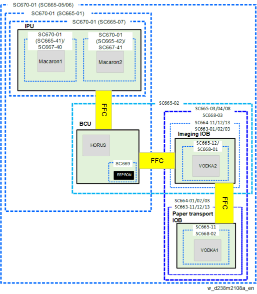
[*]WHEN SC670 (ENGINE START UP ERROR) IS DISPLAYED
Causes
The engine board resets at an unexpected time, and does not start up again.
Solutions
Note: CTL = Controller
SC670-01
Engine start up error when the machine boots up
If the symptom occurs, use the following chart to decide the best course of action.

SC670-02
Engine start up error when the machine is in operation.
Replace the part in order of precedence stated below (since there is a high possibility that those parts are broken and causing the error).
- Replace BCU
- Replace IPU
- Replace CTL
- Replace PSU
SC670-03
Replace the part in order of precedence stated below (since there is a high possibility that those parts are broken and causing the error).
- Replace IPU
- Replace CTL
- Replace PSU
- Replace BCU.
SC670-04
Replace the part in order of precedence stated below (since there is a high possibility that those parts are broken and causing the error).
- Replace IPU
- Replace BCU
- Replace CTL
Troubleshooting
- Replace PSU
WHEN SC672 (CONTROLLER START UP ERROR) IS DISPLAYED
Symptom
Note: CTL = Controller The following occur:
SC672-00Communication error between operation panel and CTL after machine is powered on.
SC672-10Communication error (receive) between operation panel and CTL after machine is powered on.
SC672-11Communication error (send) between operation panel and CTL after machine is powered on.
SC672-12Communication error between operation panel and CTL after normal start-up.
SC672-13Communication error between operation panel and CTL after normal start-up; Operation panel not detected.
- SC672 does not appear on the SMC report, as it is not logged.
- The Smart Operation Panel communicates with the controller via a USB cable and IPU. SC672 is triggered when the panel cannot communicate with the controller.
Causes
Possible causes of SC672 include:- USB communication path failure (USB cable, IPU)
- CTL boot up error and/or operation panel boot up error due to abnormal break in operations of CTL.
Possible causes of operation panel cannot light include: - USB communication path failure (USB cable, IPU)
- Operation panel cannot communicate with CTL due to CTL boot-up error

[A]: Operation Panel : IPU
[C]: FCU
[D]: Controller [E]: USB cable
Solutions
Do the following.
Turn the machine power OFF/ON.
Do the action in the flowchart below to determine the cause and best course of action when SC672 occurs.
- If the SC recurs after you do the action in this flowchart, do the following.
- If SC819 (cache error) appears in the SC history, replace the controller board.
- If SC991 (SCS: scs time count level c’) appears in the SC history, replace the controller board and USB cable.
- If the SC recurs after you do the action in this flowchart, do the following.

Parts How to determine the cause USB cable LED on CTL blinks for 1 second Operation panel LED on CTL blinks for 1 second CTL LEDs on CTL blink constantly Memory LEDs on CTL blink constantly
Troubleshooting
Flowchart to determine parts to replace when no display on operation panel

Parts How to determine the cause USB cable LED on CTL blinks for 1 second Operation panel LED on CTL blinks for 1 second IPU Fuse 3 on the IPU CTL LED on CTL does not blink Memory LED on CTL does not blink
Troubleshooting
[A]: LEDs on the controller board
Check the condition (lit, off, blinking) of the LED on the CTL.
LED /POSTCODE AREA on the CTL

Normal situation: POSTCODE LED 8 and BIOS LED blinking for 1 second

No. Note LED For CPU - POSTCODE 8 and LED16 blink when the CPU is operating normally.
- POSTCODE 8 and LED16 is lit or off when there is a problem with the CPU.
: Abnormal mode: LEDs on the controller board
LEDs 1 to 8 blink constantly

No. Note POSTCODE 1-8 and LED 8 blinks. LED 8 is lit or off when there is a problem with the CPU. LED 16 - For self-diagnosis code (BIOS).
- After the BIOS starts up, LEDs 4,5,7 turn off and LEDs 1,2,3 ,6 turn on
- LED is lit when the BIOS is running.
- LED blinks when the OS is running.
[C]: Reconnecting and replacing the USB cable
1. Re-connect the USB cable between IPU board and operation panel.

When connecting the cable, hold the molded part of the cable as shown below so as not to apply excessive force on the connector part. Applying excessive force toward the upper direction on the connector may cause connection failure.

Troubleshooting
Applied to machines built in October 2016 and later:
A bracket [A] which covers the upper part of the cable will be added.

PCB for the operation panel

USB connector (IPU)

[D]: Replacing the Memory
Turn the machine power OFF.
Attach the memory on the CTL as shown (in a vertical orientation).

Lock the hook.

[E]: CMOS clear
Turn the machine power OFF.
Turn Dip switch 1-3 ON for 10 seconds
Turn Dip switch 1-3 OFF
Turn the machine power ON.

Troubleshooting
[F]: Fuse on the IPU
Fuse on the IPU

[G]: Replacing the USB cable and the operation panel
Remove the Platen Cover, or ARDF/SPDF. (page 4-30)
Remove a screw at the scanner right cover.

Remove the scanner right cover [A]
Remove the hook at the upper part, and then slide the cover in the rear direction.

Remove the scanner front cover [A]
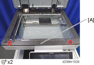
Remove the scanner left cover [A]

Holding down both the sides of the operation panel upper cover [A], unhook the tabs (indicated by blue circles) and remove the cover.

Troubleshooting
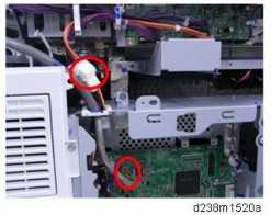
Remove the USB cable connector [A]
x1, x2).
x2).
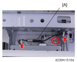
Remove the two screws
x2).
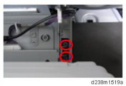
Remove the two connectors
x2).
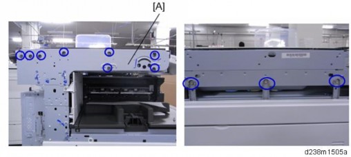
Remove the scanner unit [A]
x11).
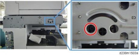
Never loosen or remove the following screw when you remove or re-attach the unit. This screw fixes the scanner cam in place. If the position of the scanner cam changes, the scanner will be misaligned. This will result in image skew and other image alignment issues.
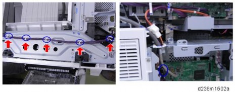
Remove the USB cable
x5)
Applied to machines built in May 2016 and later: A clamp on the IPU [A] will be added.
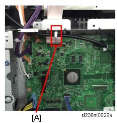
Troubleshooting
- Make sure that there is no space between the machine frame and the following three areas of the scanner unit when you re-attach the scanner unit.
[*]SC sub code (SC672-10 or 99)
[*]Date/time of problem occurrence
[*]Factor(s) that trigger the problem (ex. SC672-11 occurred 3 minutes after tuning ON the main power switch.)
[*]Occurrence frequency (ex. One out of ten times when turning ON the main power switch)
[*]Parts replaced
[*]Date/time when parts were replaced
Troubleshooting
[*]Check the abnormal noise of the drive unit (peripheral fusing)WHEN ABNORMAL NOISE OCCURS
When abnormal noise occurs during machine operating, identify the occurrence location, by using various OUTPUT Check. However, about the following two modules, follow the checking procedure flow.
[*]Check the abnormal noise when the toner is supplied or the bottle motor is driving
- Because the damage or contamination of parts can lead to secondary failure, always follow the procedure.
- Take particular care not to be caught in the rotating parts of the motors and/or gears.
PROCEDURE OF CHECKING ABNORMAL NOISE OF DRIVE UNIT (PERIPHERAL FUSING)
When the abnormal noise of drive unit (peripheral fusing) has occurred, follow the following flow, and check whether the fusing unit is the cause, by using SP1-153 (Abnormal Noise Confirmation). If the fusing unit is the cause, replace the fusing unit. If the drive module is the cause, in addition perform the operation check of various motors by using OUTPUT Check, to identify which motor is the cause.
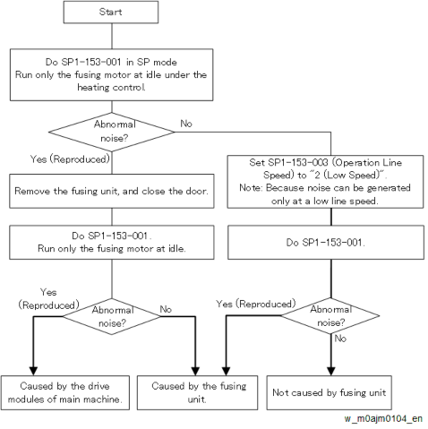
About the setting value of the operation line speed in SP1-153-003
During warming-up or operating on the operation panel, the motors rotate at low line speeds. At the time, if noise occurs, start checking from [2: Low Speed]. Middle speed is for only thick paper 1 printing, so use middle speed if abnormal noise occurs when thick paper 1 is supplied.
Related SP
SP No. SP Name Function Description SP1-153-001 Abnormal Noise Confirmation: Unit: Execute The fusing motor rotates with the heating control. Fails if the fusing unit is not installed or the cover is open SP1-153-002 Abnormal Noise Confirmation: No Unit: Execute The fusing motor rotates without the fusing unit. Fails if the fusing unit is installed or the cover is open TroubleshootingSP No. SP Name Function Description SP1-153-003 Abnormal Noise Confirmation: Operation Line Speed Line speed at the time of rotation
0: Standard speed
1: Middle speed
2: Low speedSP1-153-004 Abnormal Noise Confirmation: Operation Time Rotates during this time. Initial value: 60 sec. SP1-153-005 Abnormal Noise Confirmation: Heat Center Target Temp Temperature setting for SP1-153-001 (Unit:
Execute)Do not change SP1-153-006 Abnormal Noise Confirmation: Heat End Target Temp Temperature setting for SP1-153-001 (Unit:
Execute)SP1-153-007 Abnormal Noise Confirmation: Press Target Temp Temperature setting for SP1-153-001 (Unit:
Execute)
OPERATION CHECK PROCEDURES OF THE TONER SUPPLY MOTOR/TONER BOTTLE DRIVE MOTOR
The operation check of the toner supply motor and/or toner bottle drive motor, is performed by a forced toner supply, not OUTPUT Check.
- Operation other than the following procedures may occur the abnormal density, toner scattering, scumming, and cleaning failure at the image transfer unit.
Do [Force Tnr Supply :Exe (SP3-050-003 to 006)] for the applicable color twice. If there is enough toner in the toner supply unit, the toner bottle drive motor will not work.
SP No. SP Name SP3-050-003 Force Tnr Supply :Exe Execute: K SP3-050-004 Force Tnr Supply :Exe Execute: C SP3-050-005 Force Tnr Supply :Exe Execute: M SP3-050-006 Force Tnr Supply :Exe Execute: Y
Do [Manual ProCon :Exe Density Adjustment (SP3-011-002)] once.
- If the operation of the toner bottle drive motor could not be checked, do step1 again after the manual execution of density adjustment.
JAM DETECTION
JAM DISPLAY
When a jam occurs, the cause position will blink.
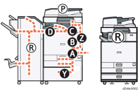
CLEARING A PAPER JAM
- Do not touch any components except the specified parts for removing jammed paper. Some parts can burn you because they become hot during operation.
- Do not turn the power off during removal of jammed paper. If you turned the power off, functions or values that were previously set will be deleted.
- Be sure not to tear paper up, and that you remove all pieces. Remaining scraps of paper in the machine could cause another paper jam or machine failure.
- If there are multiple jam locations, check all the locations that are displayed at the same time.
See the decals on the machine for how to remove jammed paper.
- Do not touch any components except the specified parts for removing jammed paper. Some parts can burn you because they become hot during operation.
PAPER JAM HISTORY
History Checking Method
Plotter (print engine) jam history can be displayed using SP7-507.
[*]SP7-507-002 "Plotter Jam: History Latest1"
[*]SP7-507-003 "Plotter Jam: History Latest2"
[*]SP7-507-004 "Plotter Jam: History Latest3"
[*]SP7-507-005 "Plotter Jam: History Latest4"
[*]SP7-507-006 "Plotter Jam: History Latest5"
[*]SP7-507-007 "Plotter Jam: History Latest6"
[*]SP7-507-008 "Plotter Jam: History Latest7"
[*]SP7-507-009 "Plotter Jam: History Latest8"
[*]SP7-507-010 "Plotter Jam: History Latest9"
Paper Jam Display

[*]CODE: Indicates the jam code.
[*]SIZE: Indicates the paper size code.
[*]TOTAL: Indicates the total counter (SP7-502-001).
[*]DATE: Indicates the date when the jam occurred.
- The jam history of the 10 latest jams is displayed.
- The first jam is not included in the history record.
JAM CODES AND DISPLAY CODES
- Cause code: Jam cause code displayed by log data
- Display code: Jam position displayed on control panel
Late jam
The paper has failed to arrive within the prescribed time due to a jam that has occurred upstream of the referenced sensor.
Lag jam
The paper has failed to leave the location of the referenced sensor within the prescribed time due to a jam downstream of the referenced sensor.
Troubleshooting
Stay jam
The paper is within the location of the referenced sensor.
ARDF DF3090
Cause code
Cause of jamLate Jam Lag Jam Stay Jam Display code 014 Skew Correction Sensor

P 064 Skew Correction Sensor

P 016 Registration Sensor

P 066 Registration Sensor

P 017 Exit Sensor

P 067 Exit Sensor

P 239 Misfeed: Original Removed

P
SPDF DF3100
Cause code
Cause of jamLate Jam Lag Jam Stay Jam Display code 013 Separation Sensor

P 063 Separation Sensor

P 014 Skew Correction Sensor

P 064 Skew Correction Sensor

P 015 Pre-Scanning Entrance Sensor

P 065 Pre-Scanning Entrance Sensor

P 016 Registration Sensor

P 066 Registration Sensor

P 017 Exit Sensor

P 067 Exit Sensor

P 239 Misfeed: Original Removed

P Cause code
Cause of jamLate Jam Lag Jam Stay Jam Display code 001 Initial jam

P 001 Overload jam

P
Main Machine
Cause code
Cause of jamLate Jam Lag Jam Stay Jam Display code 001 Transport Sensor 1

A 001 Transport Sensor 2

A 001 Registration Sensor

B 001 Fusing Entrance Sensor

C 001 Fusing Exit Sensor

C 001 Paper Exit Sensor

C 001 Reverse Sensor

C 001 Duplex Exit Sensor

Z 001 Duplex Entrance Sensor

Z 003 Paper not fed from tray 1

A1 004 Paper not fed from tray 2

A2 008 Paper not fed from bypass tray

A 009 Paper not transported to duplex unit

Z
096Disappearance of the detection Timing
Only remaining paper position information displayed011 Transport Sensor 1

A 012 Transport Sensor 2

A 017 Registration Sensor

A 018 Fusing Entrance Sensor

B Cause code
Cause of jamLate Jam Lag Jam Stay Jam Display code 019 Fusing Exit Sensor

C 020 Paper Exit Sensor

C
051Transport Sensor 1 (when paper not fed from Tray 1)

A 052 Transport Sensor 2

A
048Transport Sensor 1 (when paper not fed from Bypass Tray)

A 057 Registration Sensor

B 060 Paper Exit Sensor

C 024 Reverse Sensor

C 064 Reverse Sensor

C 025 Duplex Exit Sensor

Z
025Duplex Exit Sensor & No Paper at Duplex Entrance Sensor

Z 065 Duplex Exit Sensor

Z 027 Duplex Entrance Sensor

C
027Duplex Entrance Sensor & No Paper at Reverse Sensor

Z 067 Duplex Entrance Sensor

A
Troubleshooting
Paper Feed Unit PB3150
Cause code
Cause of jamLate Jam Lag Jam Stay Jam Display code 005 Paper not fed from tray 3

Y1 013 Vertical Transport Sensor (Tray 3)

Y 053 Vertical Transport Sensor (Tray 3)

Y Cause code
Cause of jamLate Jam Lag Jam Stay Jam Display code 001 Vertical Transport Sensor (Tray 3)

Y
Paper Feed Unit PB3220/PB3210
Cause code
Cause of jamLate Jam Lag Jam Stay Jam Display code 005 Paper not fed from tray 3

Y1 013 Vertical Transport Sensor (Tray 3)

Y 053 Vertical Transport Sensor (Tray 3)

Y 001 Vertical Transport Sensor (Tray 3)

Y 006 Paper not fed from tray 4

Y2 014 Vertical Transport Sensor (Tray 4)

Y 054 Vertical Transport Sensor (Tray 4)

Y 001 Vertical Transport Sensor (Tray 4)

Y
Bridge Unit BU3070
Cause code
Cause of jamLate Jam Lag Jam Stay Jam Display code 021 Paper Exit Sensor (Bridge Unit)

D 022 Relay Transport Sensor (Bridge Unit)

D 061 Paper Exit Sensor (Bridge Unit)

D 062 Relay Transport Sensor (Bridge Unit)

D
Troubleshooting
Internal Finisher SR3130
Cause code
Cause of jamLate Jam Lag Jam Stay Jam Display code 100 Inlet Sensor

R1-R2 101 Inlet Sensor

R1-R2 102 Transport sensor

R1-R2 103 Transport sensor

R1-R2 104 Paper Exit Unit

R1-R2 105 Jogger fence motor (front)

R1-R2 106 Jogger fence motor (rear)

R1-R2 107 Shift Roller Motor

R1-R2 108 Positioning Roller Motor

R1-R2 109 Paper Exit Guide Plate Open/Close Motor

R1-R2 110 Stapler Retreat Motor

R1-R2 111 Shift Tray Ascent/Descent Motor

R1-R2 112 Stapler Motor

R1-R2 113 Paper Press Motor

R1-R2 114 Punch Motor

R1-R2 115 Punch Displacement Motor

R1-R2 116 Horizontal Registration Displacement Motor

R1-R2 148 Paper exit end not responding

R1-R2 149 Main instruction data defect

R1-R2 Booklet Finisher SR3220
Cause code
Cause of jamLate Jam Lag Jam Stay Jam Display code 200 Paper Entrance

R1-R4 201 Paper Entrance

R1-R4 202 Proof Exit

R1-R4 203 Proof Exit

R1-R4 204 Intermediate transport (right)

R1-R4 205 Intermediate transport (left)

R1-R4 206 Intermediate transport (left)

R1-R4 207 Shift Exit

R1-R4 208 Shift Exit

R1-R4 209 Stack Transport

R5-R10 210 Rear Edge Stopper Transport

R5-R10 211 Rear Edge Stopper Transport

R5-R10 212 Paper did not reach middle folding exit

R5-R10 213 Middle Folding exit

R5-R10 220 Jam in inlet transport motor


R1-R4 221 Jam in proof transport motor


R1-R4 222 Jam in exit transport/positioning/approach roller motor


R1-R4 223 Jam in shift motor


R1-R4 224 Jam in jogger motor


R1-R4 225 Jam in exit guide plate open/close motor


R1-R4 226 Jam release motor


R1-R4 TroubleshootingCause code
Cause of jamLate Jam Lag Jam Stay Jam Display code 227 Jam in tray ascent/descent motor


R1-R4 228 Jam in positioning roller motor


R1-R4 229 Jam in stapler retreat motor


R1-R4 230 Jam in stapler motor


R1-R4 231 Jam in punch system motor


R1-R4 232 Jam in stack transport motor


R5-R10 233 Jam in rear edge stopper motor


R5-R10 234 Jam in folding brade motor


R5-R10 235 Jam in paper exit guide drive motor


R1-R4
236Jam in stapleless stapler transfer motor


R1-R4 237 Jam in staple motor (stapleless)


R1-R4 238 Jam in paper guide motor


R1-R4 248 Paper exit end is not responding


R1-R4 249 Main instruction data defect


R1-R4
Internal Finisher SR3180
Cause code
Cause of jamLate Jam Lag Jam Stay Jam Display code 300 Entrance sensor

R 301 Entrance sensor

R 302 Paper exit sensor

R 303 Paper exit sensor

R 304 Shift motor

R 305 Junction gate motor

R 306 Paper exit pressure release motor

R 307 Stapler motor

R 348 Paper exit end not responding

R
PAPER SIZE CODE
Size Code Paper Size Size Code Paper Size 005 A4 LEF 141 B4 SEF 006 A5 LEF 142 B5 SEF 014 B5 LEF 160 DLT SEF 038 LT LEF 164 LG SEF 044 HLT LEF 166 LT SEF 132 A3 SEF 172 HLT SEF 133 A4 SEF 255 Others 134 A5 SEF
Troubleshooting
SENSOR LOCATIONS
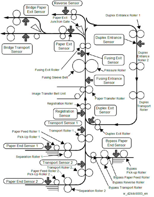
TROUBLESHOOTING FOR TRANSPORT/PAPER FEEDING OF THE MACHINE
CURLED PAPER
Make sure that the following SPs are set to their default values, and keep them at these values at all time.
SP1-113-001 (Curl Correction): Keep at default value of 0 (OFF)
This is because printing productivity drops to about 65 to 80% when this SP is ON. It is not effective in reducing curl on these models.
[*]SP1-115-xxx (Print Target Temp): Keep at default value.
This is because fusing offset may occur when the fusing temperature is reduced. This SP is not effective for improving image quality on these models.
Solution:
Installing the tray heaters for the mainframe paper bank and optional paper banks. (page 2-58 "Anti-Condensation Heater for Paper Feed Trays")
[*]Clean the sensor.INITIAL JAM
If the error occurs periodically, do the following steps. If the result is as shown in the "Problem Judgement" column, follow the solutions.
Initial Jam: Cause Code 001 / Location Code A
Target Part/SP No.: Transport Sensor (1st Feed Tray) / SP5-803-003 (Transport Sensor 1)
Cause verification Problem Judgement Execute an INPUT check when there is no paper at the position of the referenced sensor. 0: Paper detected Execute an INPUT check when there is paper at the position of the referenced sensor. 1: Paper not detected
Solution:
[*]Reconnect the connector.
[*]Replace the sensor.
[*]Replace the Paper Transport IOB.
[*]Replace the harness.
Troubleshooting
Target Part/SP No.: Transport Sensor (2nd Feed Tray) / SP5-803-005 (Transport Sensor 2)
Cause verification Problem Judgement Execute an INPUT check when there is no paper at the position of the referenced sensor. 0: Paper detected Execute an INPUT check when there is paper at the position of the referenced sensor. 1: Paper not detected
Solution:
[*]Clean the sensor.
[*]Reconnect the connector.
[*]Replace the sensor.
[*]Replace the Paper Transport IOB.
[*]Replace the harness.
Initial Jam: Cause Code 001 / Location Code B
Target Part/SP No.: Registration Sensor / SP5-803-001
Cause verification Problem Judgement Execute an INPUT check when there is no paper at the position of the referenced sensor. 0: Paper detected Execute an INPUT check when there is paper at the position of the referenced sensor. 1: Paper not detected
Solution:
[*]Clean the sensor.
[*]Reconnect the connector.
[*]Replace the sensor.
[*]Replace the Paper Transport IOB.
[*]Replace the harness.
Initial Jam: Cause Code 001 / Location Code C
Target Part/SP No.: Fusing Entrance Sensor / SP5-803-006
Cause verification Problem Judgement Execute an INPUT check when there is no paper at the position of the referenced sensor. 0: Paper detected Execute an INPUT check when there is paper at the position of the referenced sensor. 1: Paper not detected
Solution:
[*]Clean the sensor.
[*]Reconnect the connector.
[*]Replace the sensor.
[*]Replace the Paper Transport IOB.
[*]Replace the harness.
Target Part/SP No.: Fusing Exit Sensor / SP5-803-007
Cause verification Problem Judgement Execute an INPUT check when there is no paper at the position of the referenced sensor. 0: Paper detected Execute an INPUT check when there is paper at the position of the referenced sensor. 1: Paper not detected
Solution:
[*]Clean the sensor.
[*]Reconnect the connector.
[*]Replace the sensor.
[*]Replace the Paper Transport IOB.
[*]Replace the harness.
Target Part/SP No.: Paper Exit Sensor / SP5-803-008
Cause verification Problem Judgement Execute an INPUT check when there is no paper at the position of the referenced sensor. 0: Paper detected Execute an INPUT check when there is paper at the position of the referenced sensor. 1: Paper not detected
Troubleshooting
Solution:
[*]Clean the sensor.
[*]Reconnect the connector.
[*]Replace the sensor.
[*]Replace the Paper Transport IOB.
[*]Replace the harness.
Target Part/SP No.: Reverse Sensor / SP5-803-009 (Inverter Sensor)
Cause verification Problem Judgement Execute an INPUT check when there is no paper at the position of the referenced sensor. 0: Paper detected Execute an INPUT check when there is paper at the position of the referenced sensor. 1: Paper not detected
Solution:
[*]Clean the sensor.
[*]Reconnect the connector.
[*]Replace the sensor.
[*]Replace the Paper Transport IOB.
[*]Replace the harness.
Initial Jam: Cause Code 001 / Location Code Z
Target Part/SP No.: Duplex Entrance Sensor / SP5-803-011
Cause verification Problem Judgement Execute an INPUT check when there is no paper at the position of the referenced sensor. 0: Paper detected Execute an INPUT check when there is paper at the position of the referenced sensor. 1: Paper not detected
Solution:
[*]Clean the sensor.
[*]Reconnect the connector.
[*]Replace the sensor.
[*]Replace the Paper Transport IOB.
[*]Replace the harness.
Target Part/SP No.: Duplex Exit Sensor / SP5-803-010
Cause verification Problem Judgement Execute an INPUT check when there is no paper at the position of the referenced sensor. 0: Paper detected Execute an INPUT check when there is paper at the position of the referenced sensor. 1: Paper not detected
Solution:
[*]Clean the sensor.
[*]Reconnect the connector.
[*]Replace the sensor.
[*]Replace the Paper Transport IOB.
[*]Replace the harness.
If the error occurs periodically, do the following steps. If the result is as shown in the "Problem Judgement" column, follow the solutions.JAM
Bypass No Feeding: Cause Code 008
Target Part/SP No.:Bypass/Duplex motor / SP5-804-071 (Duplex Bypass Motor: CW: Standard Speed)
Cause verification Problem Judgement Turn the referenced motor OFF with OUTPUT Drive sound heard Turn the referenced motor ON with OUTPUT Drive sound not heard
Solution:
[*]Reconnect the connector.
[*]Replace the motor.
[*]Replace the Paper Transport IOB.
[*]Replace the harness.
[*]Replace the harness.
Troubleshooting
Checking paper status, pick-up roller, feed roller, and friction roller for bypass tray
Check the paper position (Check whether or not the leading edge of the paper, side paper guide, and end paper guide are positioned according to the manual.) Check if the paper has reached the maximum stackable limit of the side paper guide. Reduce the paper to below the stackable limit. Check if the sheets are stuck to each other due to edge roughness, coating, stain, or temperature. Fan the paper Check if extra thin paper or thick paper exceeding the supported paper thickness is being used. Use a supported paper type. Check if the paper thickness and size are detected correctly. Set the paper thickness and size to the correct value. Check if the paper being used produces a lot of paper dust. Change the paper type (if possible). Check if the paper roller is stained with paper dust. Clean the pick-up roller, feed roller, and friction roller for bypass tray. - Check the paper orientation.
- Turn the paper in the feed tray upside down.
Tray 1 Transport Sensor: Late Jam : Cause Code 011
Target Part/SP No.:Transport Sensor (1st Feed Tray) / SP5-803-003 (Transport Sensor 1)
Cause verification Problem Judgement Execute an INPUT check when there is no paper at the position of the referenced sensor. 0: Paper detected Execute an INPUT check when there is paper at the position of the referenced sensor. 1: Paper not detected
Solution:
[*]Clean the sensor.
[*]Reconnect the connector.
[*]Replace the sensor.
[*]Replace the Paper Transport IOB.
[*]Replace the harness.
Target Part/SP No.:Bypass pick-up Solenoid / SP5-803-016 (Bypass Pickup Solenoid)
Cause verification Problem Judgement Turn the referenced solenoid OFF with OUTPUT check Drive sound heard Turn the referenced solenoid ON with OUTPUT check Drive sound not heard
Solution:
[*]Reconnect the connector.
[*]Replace the solenoid.
[*]Replace the Paper Transport IOB.
[*]Replace the harness.
Checking paper status, pick-up roller, feed roller, and friction roller for 1st feed tray
Check the paper position (Check whether or not the leading edge of the paper, side paper guide, and end paper guide are positioned according to the manual.) Check if the paper has reached the maximum stackable limit of the side paper guide. Reduce the paper to below the stackable limit. Check if the sheets are stuck to each other due to edge roughness, coating, stain, or temperature. Fan the paper Check if extra thin paper or thick paper exceeding the supported paper thickness is being used. Use a supported paper type. Check if the paper thickness and size are detected correctly. Set the paper thickness and size to the correct value. Check if the paper being used produces a lot of paper dust. Change the paper type (if possible). Check if the paper roller is not stained with paper dust. Clean the pick-up roller, feed roller, and friction roller for 1st feed tray. - Check the paper orientation.
- Turn the paper in the feed tray upside down.
Tray 2 Transport Sensor : Late Jam : Cause Code 012
Target Part/SP No.:Transport Sensor (2nd Feed Tray) / SP5-803-005 (Transport Sensor 2)
Cause verification Problem Judgement Execute an INPUT check when there is no paper at the position of the referenced sensor. 0 aper detected
Execute an INPUT check when there is paper at the position of the referenced sensor. 1: Paper not detected
Solution:
[*]Clean the sensor.
[*]Reconnect the connector.
[*]Replace the sensor.
[*]Replace the Paper Transport IOB.
[*]Replace the harness.
Checking paper status, pick-up roller, feed roller, and friction roller for 2nd feed tray
Check the paper position (Check whether or not the leading edge of the paper, side paper guide, and end paper guide are positioned according to the manual.) Check if the paper has reached the maximum stackable limit of the side paper guide. Reduce the paper to below the stackable limit. Check if the sheets are stuck to each other due to edge roughness, coating, stain, or temperature. Fan the paper. Check if extra thin paper or thick paper exceeding the supported paper thickness is being used. Use a supported paper type. Check if the paper thickness and size are detected correctly. Set the paper thickness and size to the correct value. Check if the paper being used produces a lot of paper dust. Change the paper type (if possible). Check if the paper roller is not stained with paper dust. Clean the pick-up roller, feed roller, and friction roller for 2nd feed tray. - Check the paper orientation.
- Turn the paper in the feed tray upside down.
Registration Sensor : Late Jam : Cause Code 017
Target Part/SP No.:Registration Sensor / SP5-803-001
Cause verification Problem Judgement Execute an INPUT check when there is no paper at the position of the referenced sensor. 0 aper detected
Execute an INPUT check when there is paper at the position of the referenced sensor. 1: Paper not detected
Solution:
[*]Clean the sensor.
[*]Reconnect the connector.
[*]Replace the sensor.
[*]Replace the Paper Transport IOB.
[*]Replace the harness.
Checking paper status, or 1st paper transport roller.
Check if extra thin paper or thick paper exceeding the supported paper thickness is being used. Use a supported paper type. Check if the paper thickness and size are detected correctly. Set the paper thickness and size to the correct value. Check if the paper feed tray is not stained with a lot of paper dust. Clean the 1st transport roller.
Fusing Entrance Sensor : Late Jam : Cause Code 018
Target Part/SP No.:Fusing Entrance Sensor / SP5-803-011
Cause verification Problem Judgement Execute an INPUT check when there is no paper at the position of the referenced sensor. 0 aper detected
Cause verification Problem Judgement Execute an INPUT check when there is paper at the position of the referenced sensor. 1: Paper not detected
Troubleshooting
Solution:
[*]Clean the sensor.
[*]Reconnect the connector.
[*]Replace the sensor.
[*]Replace the Paper Transport IOB.
[*]Replace the harness.
Target Part/SP No.: PCU Motor: Black / ITB Drive Motor / SP5-804-136 (Transfer Drum Motor K: Standard Speed)
Cause verification Problem Judgement Turn the referenced motor OFF with OUTPUT check Drive sound heard Turn the referenced motor ON with OUTPUT check Drive sound not heard
Solution:
[*]Reconnect the connector.
[*]Replace the motor.
[*]Replace the Imaging IOB.
[*]Replace the harness.
Checking paper jam, or paper transfer unit
Check if there is no double feeding. Fan the paper. Check the edges of the discharge plate to see if it is deformed or broken. Reattach or replace the discharge plate. Fusing Exit Sensor : Late Jam : Cause Code 019
Target Part/SP No.:Fusing Exit Sensor / SP5-803-011 (Duplex Entrance Sensor)
Cause verification Problem Judgement Execute an INPUT check when there is no paper at the position of the referenced sensor. 0 aper detected
Execute an INPUT check when there is paper at the position of the referenced sensor. 1: Paper not detected
Solution:
[*]Clean the sensor.
[*]Reconnect the connector.
[*]Replace the sensor.
[*]Replace the Paper Transport IOB.
[*]Replace the harness.
Target Part/SP No.: Fusing Motor / SP5-804-092 (Fusing Motor: CW: Standard Speed)
Cause verification Problem Judgement Turn the referenced motor OFF with OUTPUT check Drive sound heard Turn the referenced motor ON with OUTPUT check Drive sound not heard
Solution:
[*]Reconnect the connector.
[*]Replace the motor.
[*]Replace the Imaging IOB.
[*]Replace the harness.
Checking paper jam, or paper transfer unit
Check if there is double feeding. Fan the paper. Check if the margin of the leading edge of paper is too narrow. Adjust the margin at the leading edge of paper with SPs. Check if the paper is a non-recommended type, e.g., inkjet paper. Replace the paper. Check if the gap between the fusing stripper plate and fusing belt is too wide, caused by deformation of the plate. Replace the fusing stripper plate. Check if there is toner and/or paper dust on the surfaces of the fusing belt and pressure roller. Clean the fusing belt. Check if the setting values, e.g. fusing temperature, are higher than the initial values. Reset the SP values to the initial values.
Troubleshooting
Paper Exit Sensor : Late Jam : Cause Code 020
Target Part/SP No.: Paper Exit Sensor / SP5-803-008
Cause verification Problem Judgement Execute an INPUT check when there is no paper at the position of the referenced sensor. 0 aper detected
Execute an INPUT check when there is paper at the position of the referenced sensor. 1: Paper not detected
Solution:
[*]Clean the sensor.
[*]Reconnect the connector.
[*]Replace the sensor.
[*]Replace the Paper Transport IOB.
[*]Replace the harness.
Target Part/SP No.
aper Exit Solenoid / SP5-804-004 (Exit Junction Solenoid)
Cause verification Problem Judgement Turn the referenced solenoid OFF with OUTPUT check Drive sound heard Turn the referenced solenoid ON with OUTPUT check Drive sound not heard
Solution:
[*]Reconnect the connector.
[*]Replace the solenoid.
[*]Replace the Paper Transport IOB.
[*]Replace the harness.
Checking paper jam, or paper status
Check if the leading edge of the paper and the paper feed guide are wet. If condensation has occurred inside the machine, leave the machine idle for a few minutes to remove condensation. Check if the paper is curled too much. If the paper is curled too much, switch on the anti-condensation heater for paper tray. Check if extra thin paper or thick paper exceeding the supported paper thickness is being used. Use a supported paper type. Check if the paper thickness and size are detected correctly. Set the paper thickness and size to the correct value.
Tray 1 Transport Sensor : Lag Jam : Cause Code 051
Target Part/SP No.:Transport Sensor (1st Feed Tray) / SP5-803-003 (Transport Sensor 1)
Cause verification Problem Judgement Execute an INPUT check when there is no paper at the position of the referenced sensor. 0 aper detected
Execute an INPUT check when there is paper at the position of the referenced sensor. 1: Paper not detected
Solution:
[*]Clean the sensor.
[*]Reconnect the connector.
[*]Replace the sensor.
[*]Replace the Paper Transport IOB.
[*]Replace the harness.
