HOME PAGE | < Previous | Contents | Next >
Smart Card Reader Built-in Unit Type M19 (D3BS-22)
Installation
Installation
Installation
2.36 SMART CARD READER BUILT-IN UNIT TYPE M19 (D3BS-22)
2.36.1 ACCESSORY CHECK
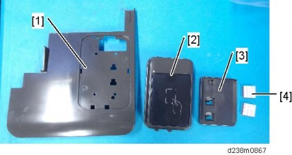
No. | Description | Q’ty | Remarks |
1 | Corner Cover | 1 | |
2 | IC Card Reader Spacer | 1 | |
3 | IC Card Reader Table | 1 | |
4 | Sponge | 2 |
2.36.2 INSTALLATION PROCEDURE
When installing this option, turn OFF the main power and unplug the power cord from the wall socket. If installing without turning OFF the main power, an electric shock or a malfunction may occur.
An IC card reader and a USB cable are not included with this unit. The customers must obtain these themselves, and the technicians must install them.
There are 2 ways to connect the USB cable of the IC card. One is to the machine USB slot which is the same way as the previous machine, and another is to the smart operation panel USB slot.
Procedure for Connecting to the Main Machine USB Slot
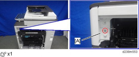
1. Open the right door, and then remove the small cover [A].
Smart Card Reader Built-in Unit Type M19 (D3BS-22)
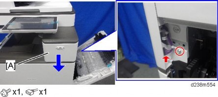
2. Remove the screw and the connector, and then remove the front upper cover [A].
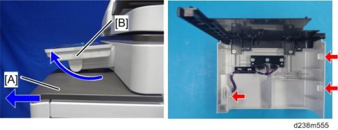
Remember that there is a tab at the positions of the red arrows.
Rotate the operation panel [B] upward to a horizontal position, and then detach the front upper cover [A].
3. Remove the original upper cover [A].
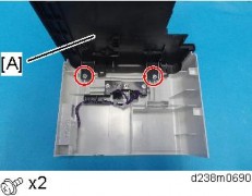
Smart Card Reader Built-in Unit Type M19 (D3BS-22)
Installation
Installation
Installation
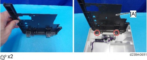
4. Attach the corner cover [A] provided with this option.
Use the screws removed in the previous step.
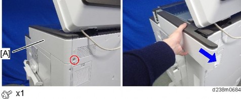
5. Remove the scanner right cover [A].
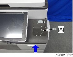
6. Reattach the front upper cover with corner cover [A] to the main machine.
7. Pass the USB cable [A] through the hole.
This cable is not included in this unit. The user may need to provide it.
Smart Card Reader Built-in Unit Type M19 (D3BS-22)
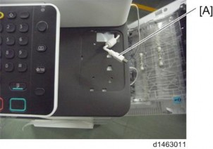
8. Attach the table [A].
There are three ribs on the back side of the table.
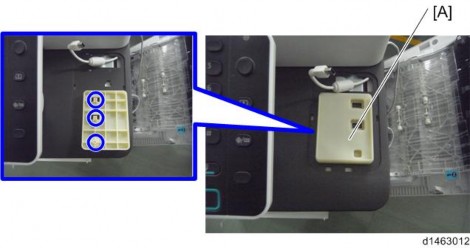
9. Attach the sponges [A] with double-sided tape.
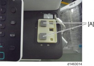
10. Connect the cable [B] to the IC reader [A] and attach the reader to the table.
Installation
Installation
Installation
Smart Card Reader Built-in Unit Type M19 (D3BS-22)
The USB cable should be turned as the following photo shows.
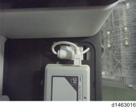
11. Attach the IC card reader cover [A].
12.
Smart Card Reader Built-in Unit Type M19 (D3BS-22)
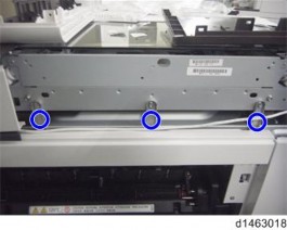
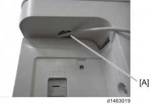
13. Remove the cover to make the hole [A] to pass the cable through.
14. Connect the USB connector to the USB interface of the controller.
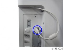
15. Route the cable as shown in the following photo.
Tuck in the excess length portion of the cable in the space over the controller box.
Installation
Installation
Installation