HOME PAGE | < Previous | Contents | Next >
Smart Card Reader Built-in Unit Type M19 (D3BS-22)
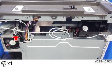
16. Reattach the exterior covers.
Procedure for Connecting to the Operation Panel USB Slot
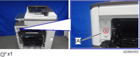
1. Open the right door, and then remove the small cover [A].
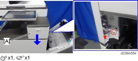
2. Remove the screw and the connector, and then remove the front upper cover [A].
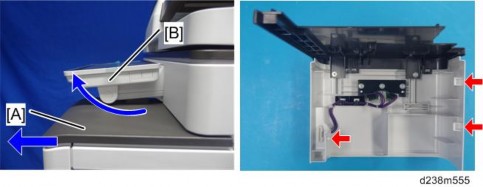
Remember that there is a tab at the positions of the red arrows.
Rotate the operation panel [B] upward to a horizontal position, and then detach the front upper cover [A].
Smart Card Reader Built-in Unit Type M19 (D3BS-22)
3. Remove the original upper cover [A].
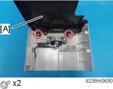
4. Attach the corner cover [A] provided with this option.
Use the screws removed in the previous step.
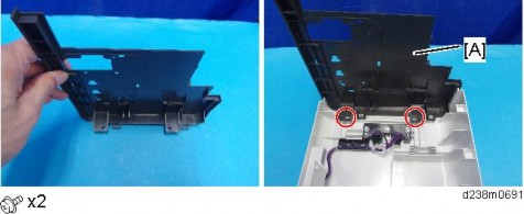
5. Remove the scanner front cover [A].
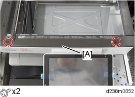
6. Remove the operation panel upper cover [A].
Installation
Installation
Installation
Smart Card Reader Built-in Unit Type M19 (D3BS-22)
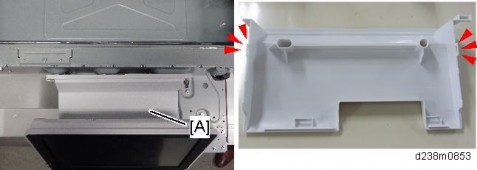
7. Remove the operation panel right cover [A].
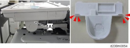
8. Thread the USB cable [B] through the notch in the front upper cover [A] and attach the ferrite core [C].
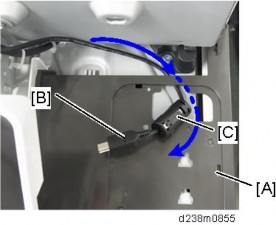
9. Reattach the front upper cover to the main machine.
10. Attach the reader spacer [A].
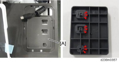
Smart Card Reader Built-in Unit Type M19 (D3BS-22)
11. Attach the sponge cushions [A] to the reader spacer.
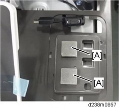
12. Connect the card reader and interface cable.
Make sure to turn the USB cable as shown so that it threads through the notch in the spacer [A].
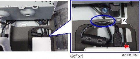
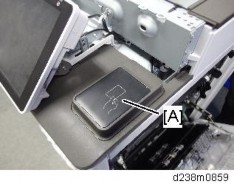
13. Attach the reader cover [A].
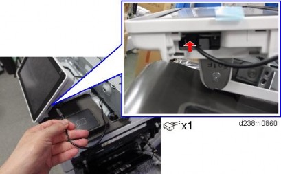
14. Connect the USB cable to the main machine’s operation panel connector.
Installation
Installation
Installation
Smart Card Reader Built-in Unit Type M19 (D3BS-22)
15. Thread the USB cable through the U-shaped groove [A] at the hinge of the operation panel and notch [B] in the cover under the cover.
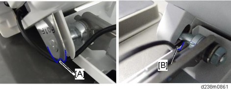
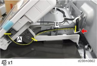
16. Apply the clamp to fasten the USB cable to the main machine.
Make sure that the cable is not loose between the connector and hinge [A] and the hinge and clamp [B].
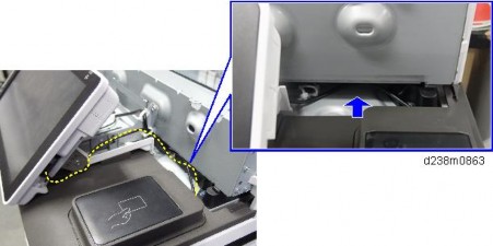
17. Tuck in the excess length portion of the USB cable in the space under the scanner.
Smart Card Reader Built-in Unit Type M19 (D3BS-22)
18. Reattach the removed covers.