HOME PAGE | < Previous | Contents | Next >
2.10.2 INSTALLATION PROCEDURE
Turn OFF the main power and unplug the power cord from the wall socket. If installing without turning OFF the main power, an electric shock or a malfunction may occur.
Do not turn the power on until you perform "adjustment after installation," or it may not start normally.
Attaching the SPDF
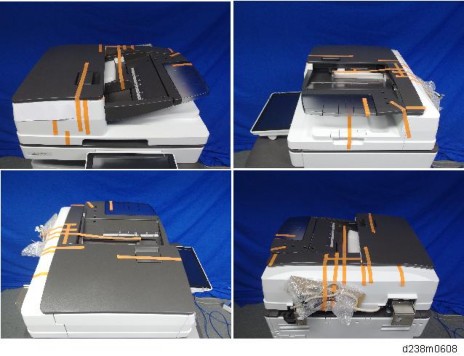
1. When unpacking, hold both sides of the SPDF and take it out of the box.

2. Place the unit on the machine temporarily, and remove the orange tapes and shipping retainers.
SPDF DF3100 (D3B0)
Installation
Installation
Installation
3. Remove the accessories in the package (boards, fixing screws, etc.).
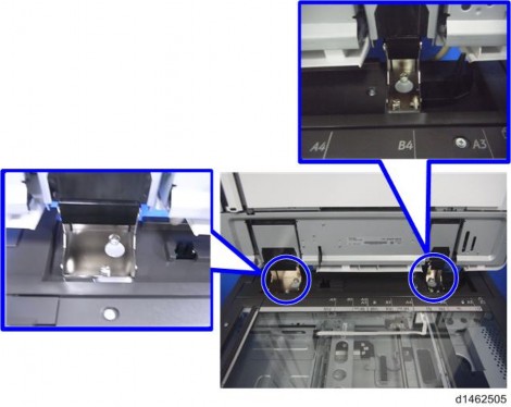
4. Attach the 2 stepped screws to the machine.
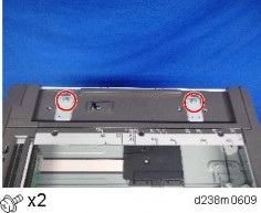
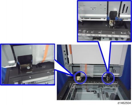
5. Align the hinges of the SPDF with the stepped screws, and attach them by sliding them in.
SPDF DF3100 (D3B0)
6. Fix the SPDF to the machine (coin screws×2)
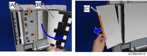
7. Release the lever [A], then open the pressure plate sheet [B], and gently remove the protective sheet [C].
8. Remove the filament tape, and shut the pressure plate sheet.
SPDF DF3100 (D3B0)
Installation
Installation
Installation
9. Remove the platen sheet [A], and set it on the exposure glass.
Align it with the left scale and rear scale of the printer.
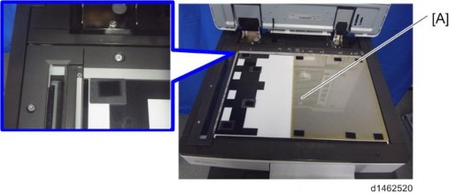
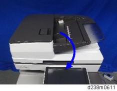
10. Close the SPDF slowly, and attach the platen sheet and SPDF.
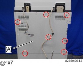
11. Remove the rear cover [A].
SPDF DF3100 (D3B0)
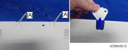
12. Remove the small disposable covers [A] on the rear cover.
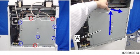
13. Remove the controller box cover [A]. Red Circle: Remove, Blue Circle: Loosen
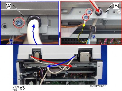
14. Connect the SPDF cable as shown and mount the brackets [A] [B] on the machine’s rear frame.
Make sure to connect the grounding wire.
SPDF DF3100 (D3B0)
Installation
Installation
Installation
15. Connect the scanner cable to the connector at the machine’s rear.
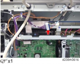
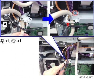
16. Attach the scanner cable [A] with the bracket on the upper frame of the controller box.
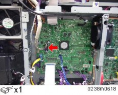
17. Connect the cable to the IPU (CN564).
SPDF DF3100 (D3B0)
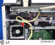
18. Tuck in the excess length portion of the cable to the back of the machine.
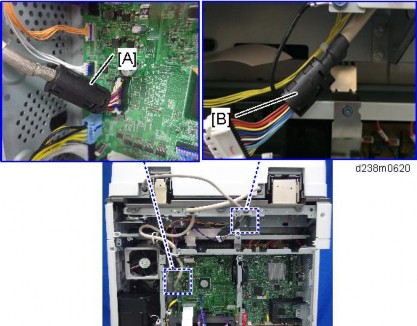
19. Attach the supplied ferrite core (L) [A] and ferrite core (S) [B].
Attach [A] close to the connector.
Attach [B] in the area near the end of the tube.
