HOME PAGE | < Previous | Contents | Next >
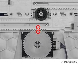
When installing, the holes must align as shown below.
4.16.7 BYPASS LENGTH SENSOR
1. Bypass tray (page 4-162)
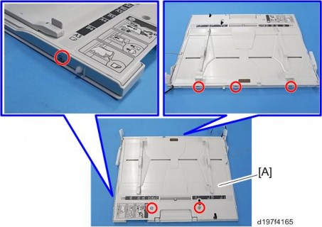
2. Six screws on the bypass tray [A] ![]() ×6).
×6).
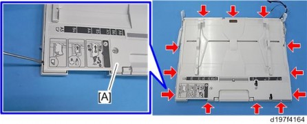
3. Release the hooks around the bypass tray [A].
Bypass Tray Unit
Replacement and Adjustment
Replacement and Adjustment
Replacement and Adjustment
There is a hook in the tray cover. Be careful not to damage it during removal or installation.
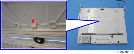
4. Release the links.
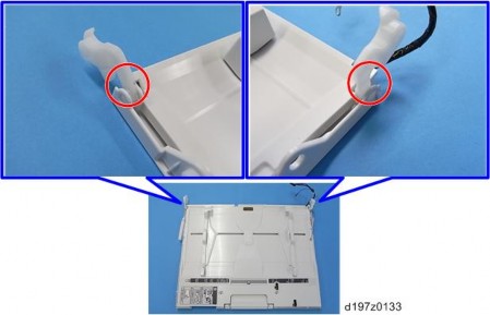
Bypass Tray Unit
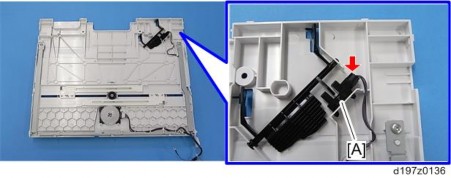
5. Bypass tray upper cover [A] (pin x 1, ![]() x1)
x1)
6.
