HOME PAGE | < Previous | Contents | Next >
4.16.6 BYPASS WIDTH SENSOR
1. Bypass tray (page 4-162)
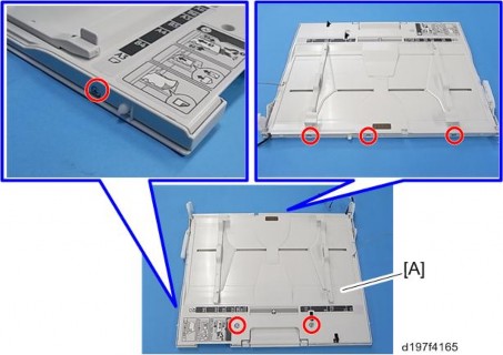
2. Six screws on the bypass tray [A] ![]() ×6).
×6).
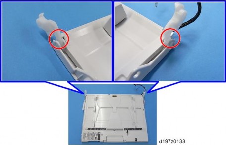
3. Release the hooks around the bypass tray [A].
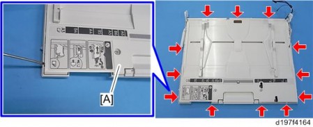
There is a hook in the tray cover. Be careful not to damage it during removal or installation.
Bypass Tray Unit
Replacement and Adjustment
Replacement and Adjustment
Replacement and Adjustment
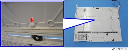
4. Release the links.
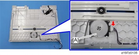
5. Bypass tray upper cover [A] (pin x 1, ![]() x1)
x1)
6.
