HOME PAGE | < Previous | Contents | Next >
Fax Option Type M19 (D3BV-01, -02, -03)
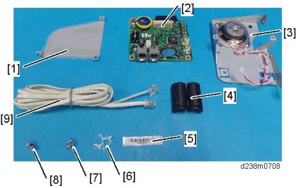
1.1.2 INSTALLATION PROCEDURE
Before installing this fax unit, print out all data in the printer buffer. Turn the main power OFF and disconnect the power cord and the network cable.
1. Remove the I/F cover [A].
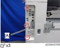
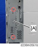
2. Remove the interface slot cover [A] ![]() x 2).
x 2).
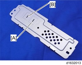
3. Remove the "TEL" [A] and "LINE1" [B] covers on the interface slot cover using a screwdriver.
FAX OPTION M19 (D3DV) FOR D243/D244
FAX OPTION M19 (D3DV) FOR D243/D244
FAX OPTION M19 (D3DV) FOR D243/D244
Fax Option Type M19 (D3BV-01, -02, -03)
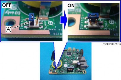
4. Switch the battery jumper switch [A] to the "ON" position.
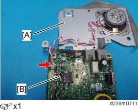
5. Connect the speaker bracket [A] to the FCU [B].
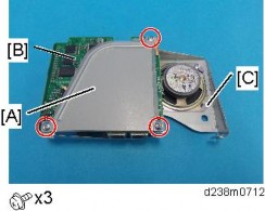
6. Attach the shield [A] to the FCU [B] and speaker bracket [C].
Fax Option Type M19 (D3BV-01, -02, -03)
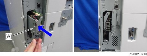
7. Insert the FCU [A] completely into the interface slot.
8. Reattach the interface slot cover [A].
Blue circle: Use the supplied screws (for the FCU)
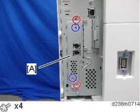
9. Reinstall the I/F cover ![]() x 3).
x 3).
10. Attach the handset support bracket and handset bracket to the machine. To install the handset, connect the handset cord with the ferrite core to the "TEL" jack.
For details about installation, refer to "Handset (D645) (Link)".
Taiwan only: Install the telephone jack cap in the "TEL" jack if the handset is not installed on the machine.
11. Make one loop with the telephone cord, and then attach the ferrite core [A] (this step is not needed for NA).
FAX OPTION M19 (D3DV) FOR D243/D244
FAX OPTION M19 (D3DV) FOR D243/D244
FAX OPTION M19 (D3DV) FOR D243/D244
Fax Option Type M19 (D3BV-01, -02, -03)
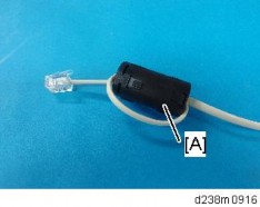
12. Connect the telephone cord to the "LINE 1" jack.
13. Attach the clamps [A] to the rear cover of the optional paper feed unit, and then hold the telephone line with the clamps as shown below.
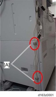
14. Attach the serial number decal under the machine serial number decal on the rear cover of the machine.
15. Attach the FCC decal to the rear cover of the machine (NA only).
16. Insert the power plug into the outlet. Turn ON the main power of the machine.
Make sure that the outlet is grounded.
"SRAM formatted" is displayed on the operation panel after the main power is turned ON. Turn the main power OFF and then ON again for normal use.
17. Make sure that the date and time are correctly set.
18. Execute SP3-102-000 in the fax SP mode and enter the serial number for the fax unit.
19. Enter the correct country code with SP1101-016(SYS OF): Country/area code for functional setting.
Fax Option Type M19 (D3BV-01, -02, -03)
Fax Stamp Installation
This procedure is needed only for machines with ARDF DF3090.
1. Open the ARDF original cover and stamp holder [A].
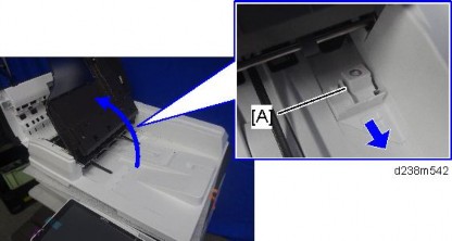
2. Install the fax stamp [A] provided with the machine.
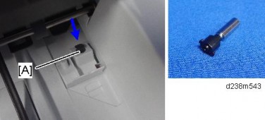
3. Close the holder.

Make sure that the holder is pushed into the position where the marks on the holder and the exterior cover face each other. If not, jam detection (J001) will occur.
4. Close the ARDF.
5. As an operation test, place the original on ARDF tray, and send it with the memory sending/fax stamp function ON.
Set the sending time to a time when nobody uses the machine (such as 11 PM).
Check if the fax stamp is marked on the trailing edge of the original.