HOME PAGE | < Previous | Contents | Next >
Booklet Finisher SR3220 (D3B9)
2.15.2 INSTALLATION PROCEDURE
When installing this option, turn OFF the main power and unplug the power cord from the wall socket. If installing without turning OFF the main power, an electric shock or a malfunction may occur.
Before installing this option, attach the "Bridge Unit BU3070 (D685)" and "Paper Feed Unit PB3220/PB3210 (D797)".
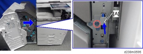
When you lift the finisher at the time of unpacking, do not hold the part [A]. Doing so may damage the frame.
Booklet Finisher SR3220 (D3B9)
Installation
Installation
Installation
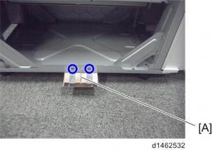
1. After unpacking, immediately attach the stabilizer [B] to prevent toppling.
Push it in thoroughly along the guide [A] until it clicks.
2.
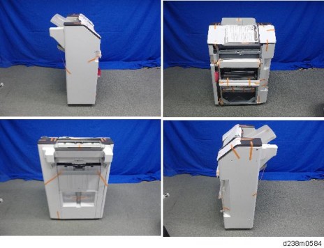
3. Remove the external orange tapes and shipping retainers.
Booklet Finisher SR3220 (D3B9)
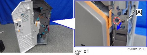
4. Open the front cover, and then remove the filament tape and packing materials.
5. Remove the fixing bracket [A].
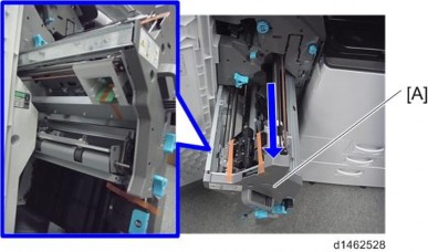
6. Pull out the saddle stitch unit [A], and remove the filament tape and packing materials.
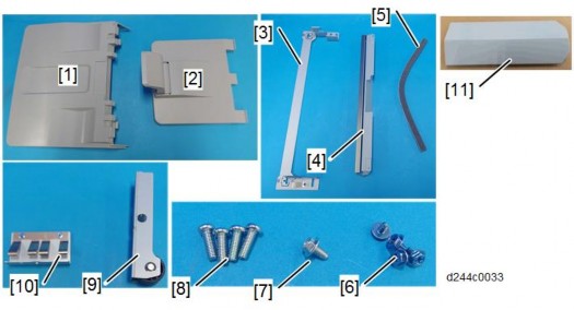
7. Remove the accessories in the package (fixing screws, etc.).
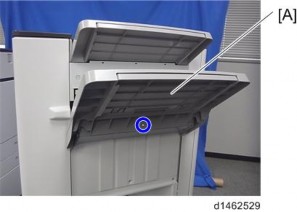
8. Attach the shift tray [A] ![]() ×1 : M4 × 8).
×1 : M4 × 8).
Booklet Finisher SR3220 (D3B9)
Installation
Installation
Installation
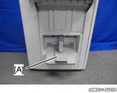
9. Attach the booklet tray [A].
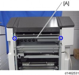
10. Attach the relay guide plate [A] ![]() ×2).
×2).
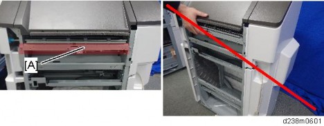
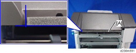
11. Clean the right side of the upper cover with a cloth moistened with alcohol, and then attach the cushion to the finisher.
Make sure that the cushion is aligned with the front-lower edge [A] of the upper cover.
Booklet Finisher SR3220 (D3B9)
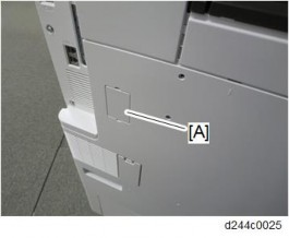
12. Remove the connector cover [A] on the rear left side of the main machine.
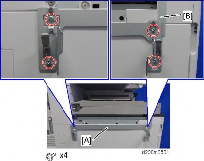
13. Attach the joint bracket [A] to the machine ![]() ×4 : 4x12).
×4 : 4x12).
Tighten the joint bracket [A] and bracket [B] of the bridge unit together.
Booklet Finisher SR3220 (D3B9)
Installation
Installation
Installation
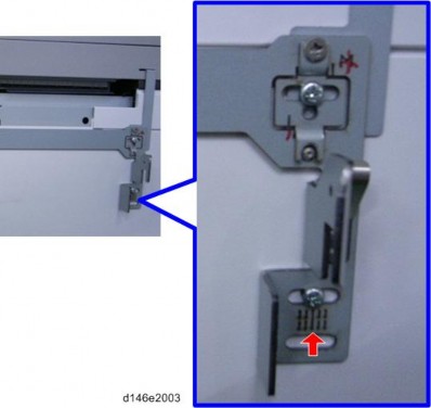
Attach the screw so that the screw head is at the center of the mark.
14. Remove the screw on the connection lever [A] and pull the lever.
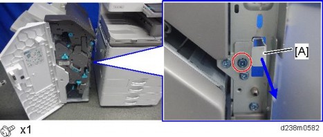
15. Connect the finisher to the main unit, and then push in the connection lever [A] to fasten it to the main unit. ![]() x1)
x1)
