HOME PAGE | < Previous | Contents | Next >
Punch Unit B702 (For B804/B805)
This is the ‘1’ position in the diagrams (the top diagram is for 2-hole punching, and the bottom diagram is for 3-hole punching).
Then, the punch drive motor turns counter-clockwise to the ‘2’ position. This movement punches the holes in the paper.
Then, the punch drive motor turns clockwise to the ‘1’ position, to be ready for the next sheet of paper.
2.8.3 PUNCH HOPPER MECHANISM

[A]: Finisher Entrance Motor (M1) [B]: Punch Waste Belt
[C]: Punch Waste Hopper
[D]: Punch Hopper Full Sensor (S4)
[A]: Finisher Entrance Motor (M1) [B]: Punch Waste Belt
[C]: Punch Waste Hopper
[D]: Punch Hopper Full Sensor (S4)
[A]: Finisher Entrance Motor (M1) [B]: Punch Waste Belt
[C]: Punch Waste Hopper
[D]: Punch Hopper Full Sensor (S4)
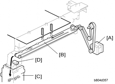
The finisher entrance motor (M1) [A] drives the timing belt and gears that rotate the punch waste belt [B].
The punchouts fall from the punch unit onto the belt. The belt moves the punchouts to the front and dumps them in the punch waste hopper [C].
The punch hopper full sensor [D]:
Signals that the hopper is full when it detects the top of the stack of punchouts that have collected in the hopper.
It also detects when the punch hopper is set properly.