1 BIN TRAY BN3110 (D3CQ)
ACCESSORY CHECK
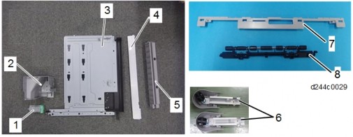
No. Description Q’ty Remarks 1 Tray 1 2 1 Bin Tray Unit 1 3 Tray support bar 1 4 Harness 1 5 Gear 1 6 Screw: M3 x 8 2 7 Harness cover 1 8 Paper support guide 1 Not used for this machine

INSTALLATION PROCEDURE
- When installing this option, turn OFF the main power and unplug the power cord from the wall socket. If installing without turning OFF the main power, an electric shock or a malfunction may occur.
- When attaching this 1-bin tray unit at the same time as Bridge Unit BU3070 or Side Tray Type M3, attach this tray first. Otherwise, the 1-bin tray’s exit tray cannot be attached due to the Bridge Unit BU3070 or Side Tray Type M3.
- To use together with the “Internal Finisher SR3130”, first attach the bottom plate of Internal Finisher SR3130, and then install the 1-bin tray.
- Remove the orange tape and shipping retainers.
- Remove the accessories (fixing screws, etc.) provided with the machine.
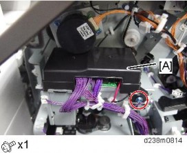
- Open the right door, and then remove the small cover [A].

- Remove the screw and connector, and then remove the front upper cover [A].

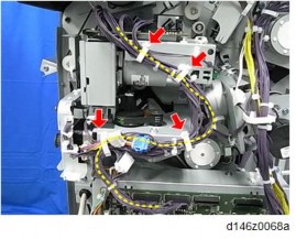
- Remember that there are three tabs at the positions of the red arrows.
- Tilt the operation panel upward to a horizontal position, and then remove the front upper cover [A].

Installation
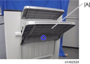
[*]Remove the paper exit tray [A].

[*]Remove the paper exit feeler [A].


[*]Open the front cover, and then remove the upper left cover [A] by pulling it towards the front×1).
[*]Remove the left rear cover [A]×2).

[*]Remove the inverter tray [A], and tray support rod cover×1).

[*]Remove the paper exit cover [A]×1).

Installation
[*]Attach the gear [A] provided with the accessories.

[*]Attach the 1-bin tray unit [A].
Make sure to engage it with the gear attached in the previous step.
Take care that the harness is not trapped between the 1-bin tray unit and the machine frame.

[*]Attach the harness provided with the accessories.

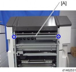
[*]Attach the tray support bar [A]×1).
When attaching the tray support bar [A], make sure that the harness attached in the previous step goes through the slit in the tray support bar circled in blue and comes outside of it as shown below.

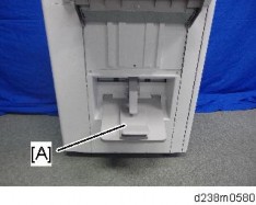
[*]Hook the 1-bin tray [A] onto the 1-bin tray unit, aligning the positions in the blue circle.

Installation
[*]Connect the harness to the 1-bin tray, and bring it around.

[*]Insert the tray support bar firmly in the 1-bin tray, and attach the harness cover [A].

[*]Reattach the left rear cover, upper left cover and front upper cover, and close the right door.
[*]Reattach the paper exit tray and paper exit feeler.
[*]Turn ON the main power.
[*]Check that output to this tray can be selected on the operation panel, and check operation.
Checking the Position of the Paper Exit Feeler
Check the following points for the paper exit feeler [A] at the paper exit.
- It can move in line with the ejection of paper
- It holds contact with the surface of the ejected paper and is still movable

Paper will get jammed in the following cases. - The paper exit feeler does not function due to obstacles (such as cables).
- The paper exit feeler does not function when the paper is pulled out and pushed back again.

Installation
- When installing this option, turn OFF the main power and unplug the power cord from the wall socket. If installing without turning OFF the main power, an electric shock or a malfunction may occur.
[*]INTERNAL SHIFT TRAY SH3070 (D691)
ACCESSORY CHECK
No. Description Q’ty 1 Tray Cover 1 2 Lever 1 Not used for this machine 3 Sheet 2

INSTALLATION PROCEDURE
- When installing this option, turn OFF the main power and unplug the power cord from the wall socket. If installing without turning OFF the main power, an electric shock or a malfunction may occur.
- The internal shift tray cannot be used together with the following peripherals:
- Side Tray Type M3 (D725)
- Internal Finisher SR 3180 (D766)
- Internal Finisher SR 3130 (D690)
- Bridge Unit BU3070 (D685)
- To use together with the "1 Bin Tray BN3110 (D3CQ)", attach the "1 Bin Tray BN3110 (D3CQ)" first before installing the internal shift tray.
- Remove the orange tapes, shipping retainers, and provided accessories (fixing screws, etc.).
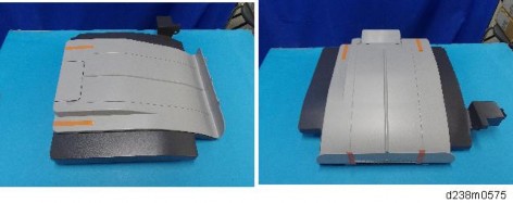
- Attach the tray cover to the shift tray [A].

[*]Remove the paper exit tray [A].

Installation
[*]Remove the connector cover [A].

[*]Attach the shift tray [A].
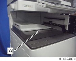
[*]Remove the paper exit feeler [A] to apply the Mylar sheet properly.
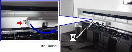
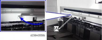
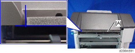
[*]Attach the sheets [A] at the edge of the paper exit cover.
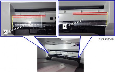
- Make sure to attach the Mylar as shown in the photo below. This is to prevent curling when the paper lands in the tray.
- The Mylar’s top edge should be 0-2.5mm from the top edge of the paper exit cover,
i.e. between the two red lines. - The Mylar's side edge should be flush against the side of the cover, i.e. along the yellow dotted line.
[*]Reattach the removed paper exit feeler [A].
[*]Do not use the lever supplied with the optional unit. Doing so may affect the stacking function.
[*]Turn ON the main power.
[*]Check that paper output to the shift tray can be selected at the operation panel, and check the operation.
Checking the Position of the Paper Exit Feeler
Check the following points for the paper exit feeler [A] at the paper exit.
- It can move in line with the ejection of paper
- It holds contact with the surface of the ejected paper and is still movable
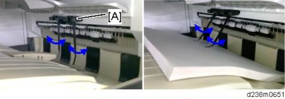
Installation
Paper will get jammed in the following cases. - The paper exit feeler does not function due to obstacles (such as cables).
- The paper exit feeler does not function when the paper is pulled out and pushed back again.
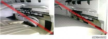
- Remove the orange tapes, shipping retainers, and provided accessories (fixing screws, etc.).
- When installing this option, turn OFF the main power and unplug the power cord from the wall socket. If installing without turning OFF the main power, an electric shock or a malfunction may occur.
[*]SIDE TRAY TYPE M3 (D725)
ACCESSORY CHECK
No. Description Q’ty 1 Left Extension Tray 1 2 Upper Extension Tray 1 3 Fixing Plate 1 4 Knob Screw 1 5 Tapping screw - M4 x 14 1 6 Tapping screw - M3 x 8 1 7 Bracket 1 8 Paper Support Guide 1 9 Driven Roller (Flat) 1
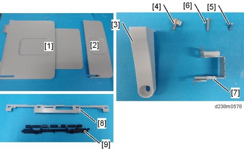
Installation
INSTALLATION PROCEDURE
- When installing this option, turn OFF the main power and unplug the power cord from the wall socket. If installing without turning OFF the main power, an electric shock or a malfunction may occur.
- The side tray cannot be used together with the following peripherals:
- Internal Shift Tray SH3070 (D691)
- Bridge Unit BU3070 (D685)
- Internal Finisher SR 3180 (D766)
- Internal Finisher SR 3130 (D690)
- To use together with the "1 Bin Tray BN3110 (D3CQ)", attach the "1 Bin Tray BN3110 (D3CQ)" first before installing the side tray.
- Remove the orange tapes, shipping retainers, and accessories (fixing screws, etc.).
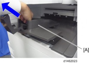
- Remove the paper exit tray [A].
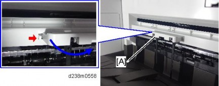
- Remove the paper exit feeler [A].
- Remove the driven roller at the machine’s exit tray and attach the supplied driven roller [A].
- Insert a flathead screwdriver into the depression in the center, and then, lifting the driven roller, unlock the part indicated by the red arrow.
- When attaching the driven roller, push its center all the way in until it clicks.
[A]: The supplied driven roller has flat rollers.
: The machine’s standard driven roller has drum-type rollers (as indicated by red frames).
Installation
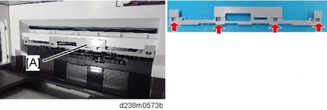
[*]Attach the paper support guide [A] (Tab x4 ).
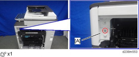
[*]Open the right door, and then remove the small cover [A].
[*]Remove the screw and connector, and then remove the front upper cover [A].
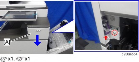
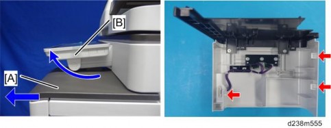
- Remember that there are three tabs at the positions of the red arrows.
- Tilt the operation panel upward to a horizontal position, and then remove the front upper cover [A].
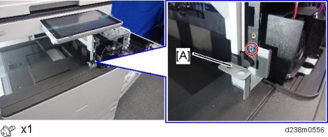
[*]Attach the bracket [A].
[*]Remove the connector cover [A].
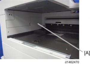
[*]Attach the bracket [A].
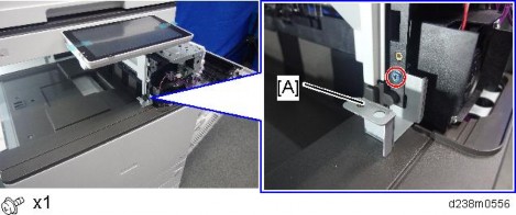
Installation
[*]Reattach the front upper cover, and close the right door.
[*]Attach the side tray unit [A] to the machine, and fix with a knob screw.
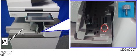
[*]Attach the fixing plate [A]×1).
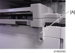
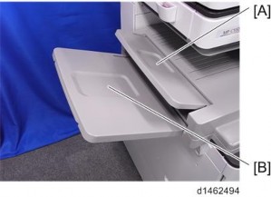
[*]Attach the upper extension tray [A] and the left extension tray .
[*]Turn ON the main power.
[*]Check that paper output to the side tray can be selected at the operation panel, and check the operation.
- Remove the orange tapes, shipping retainers, and accessories (fixing screws, etc.).
- When installing this option, turn OFF the main power and unplug the power cord from the wall socket. If installing without turning OFF the main power, an electric shock or a malfunction may occur.
[*]BRIDGE UNIT BU3070 (D685)
ACCESSORY CHECK
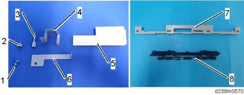
No. Description Q’ty 1 Tapping screw- M3 × 8 1 2 Screw - M4 1 3 Knob Screw - M4 1 4 Right Front Bracket 1 5 Upper Left Cover 1 6 Left Front Bracket 1 7 Paper Support Guide 1 8 Driven Roller (Flat) 1
INSTALLATION PROCEDURE
- When installing this option, turn OFF the main power and unplug the power cord from the wall socket. If installing without turning OFF the main power, an electric shock or a malfunction may occur.
- The bridge unit cannot be used together with the following peripherals:
- Internal Shift Tray SH3070 (D691)
- Side Tray Type M3 (D725)
- Internal Finisher SR 3180 (D766)
Installation
- Internal Finisher SR 3130 (D690)
- To use together with the "1 Bin Tray BN3110 (D3CQ)", attach the "1 Bin Tray BN3110 (D3CQ)" first before installing the bridge unit.
- Remove the orange tapes, shipping retainers, and provided accessories (fixing screws, etc.).
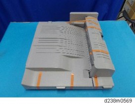
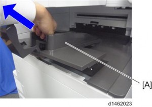
- Remove the interval tray [A].
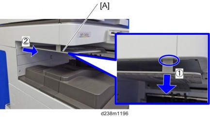
- Remove the paper exit tray [A].
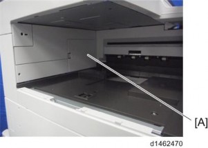
- Remove the connector cover [A].
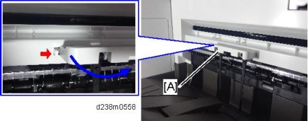
- Remove the paper exit feeler [A].
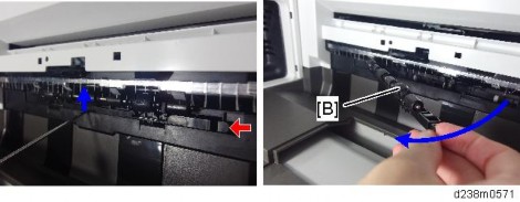
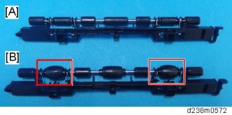
- Remove the driven roller at the machine’s exit tray and attach the supplied driven roller [A].
- Insert a flathead screwdriver into the depression in the center, and then, lifting the driven roller, unlock the part indicated by the red arrow.
- When attaching the driven roller, push its center all the way in until it clicks.
Installation
[A]: The supplied driven roller has flat rollers.
: The machine’s standard driven roller has drum-type rollers (as indicated by red frames).
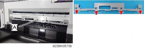
[*]Attach the paper support guide [A] (Tab x4 ).
[*]Open the front cover.
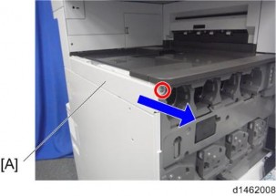
[*]Remove the upper left cover [A]×1).
- The screw removed is used again in step 15.
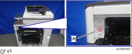
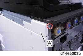
[*]Remove the screw and connector, and then remove the front upper cover [A].
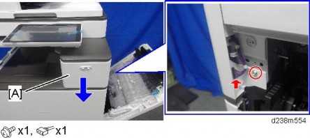
- Remember that there are three tabs at the positions of the red arrows.
- Tilt the operation panel upward to a horizontal position, and then remove the front upper cover [A].
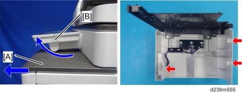
[*]Attach the right front bracket [A].
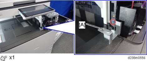
Installation
[*]Attach the bridge unit [A] to the machine.
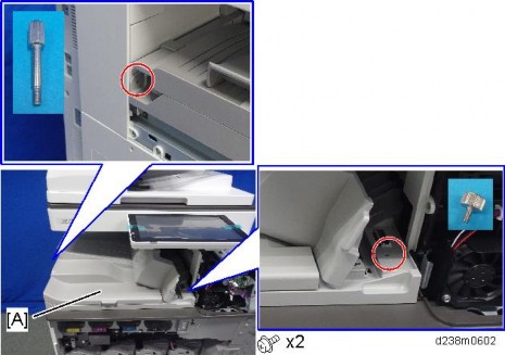
[*]Attach the front upper cover, and close the right door.
[*]Attach the upper left cover [A] provided with the accessories×1).
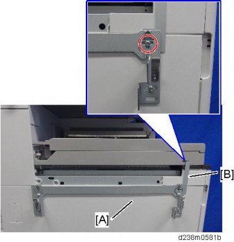
[*]Attach the L type connecting bracket [A].
To fix the bridge unit securely on the machine, tighten the finisher's joint bracket [A] and L type connecting bracket together when installing the finisher.
[*]Complete the bridge unit attachment. Refer to the procedure for connecting the optional unit downstream of the bridge unit. page 2-123 "Booklet Finisher SR3220 (D3B9)"
[*]After the finisher is installed, turn ON the main power.
[*]Check that the finisher can be selected at the operation panel.
Installation
- Remove the orange tapes, shipping retainers, and provided accessories (fixing screws, etc.).
- When installing this option, turn OFF the main power and unplug the power cord from the wall socket. If installing without turning OFF the main power, an electric shock or a malfunction may occur.
[*]BOOKLET FINISHER SR3220 (D3B9)
- To attach this optional unit, the following optional units are required.
- Bridge Unit BU3070 (D685)
- Paper Feed Unit PB3220/PB3210 (D787)
ACCESSORY CHECK
No. Description Q’ty Remarks 1 Shift Tray 1 2 Booklet Tray 1 3 Joint Bracket 1 4 Relay Guide Plate 1 5 Cushion 1 6 Tapping screws - M3 × 6 4 7 Tapping screw - M4 × 8 1 8 Screws - M4 × 12 4
9
Stabilizer
1This part must be attached to the finisher just after it is taken out of the shipping box. 10 Ground Plate 1 11 Proof Support Tray 1 - Installation Procedure: Arm 1 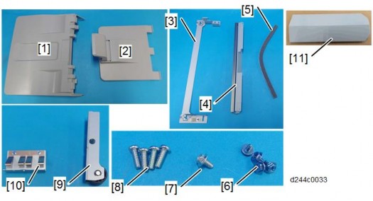
INSTALLATION PROCEDURE
- When installing this option, turn OFF the main power and unplug the power cord from the wall socket. If installing without turning OFF the main power, an electric shock or a malfunction may occur.
- Before installing this option, attach the "Bridge Unit BU3070 (D685)" and "Paper Feed Unit PB3220/PB3210 (D797)".
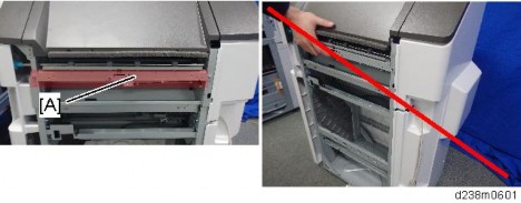
- When you lift the finisher at the time of unpacking, do not hold the part [A]. Doing so may damage the frame.
Installation
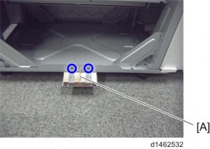
1. After unpacking, immediately attach the stabilizer to prevent toppling.
Push it in thoroughly along the guide [A] until it clicks.
Attach the ground plate [A] ( ×2).
2.
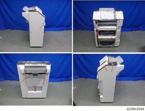
- Remove the external orange tapes and shipping retainers.
- Open the front cover, and then remove the filament tape and packing materials.
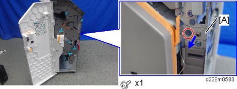
- Remove the fixing bracket [A].
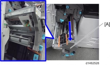
- Pull out the saddle stitch unit [A], and remove the filament tape and packing materials.
- Remove the accessories in the package (fixing screws, etc.).
- Attach the shift tray [A]
×1 : M4 × 8).

Installation
- Attach the booklet tray [A].
- Attach the relay guide plate [A]
×2).

- Clean the right side of the upper cover with a cloth moistened with alcohol, and then attach the cushion to the finisher.
- Make sure that the cushion is aligned with the front-lower edge [A] of the upper cover.
- Make sure that the cushion is aligned with the front-lower edge [A] of the upper cover.
- Remove the connector cover [A] on the rear left side of the main machine.
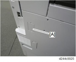
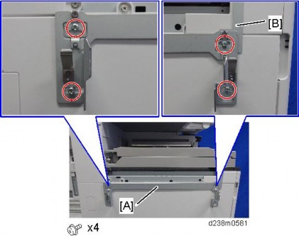
- Attach the joint bracket [A] to the machine
×4 : 4x12).

Tighten the joint bracket [A] and bracket of the bridge unit together.
Installation
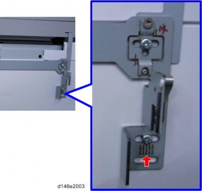
- Attach the screw so that the screw head is at the center of the mark.
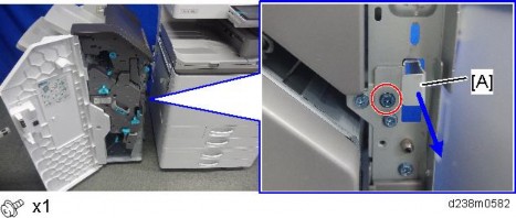
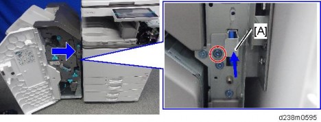
[*]Connect the finisher to the main unit, and then push in the connection lever [A] to fasten it to the main unit.x1)
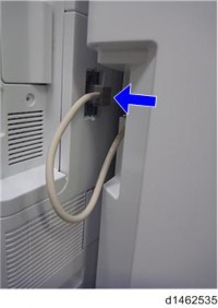
[*]Connect the interface cable to the machine.
[*]Close the front cover.
[*]Turn ON the main power.
[*]Deliver some A3/DLT paper to the proof tray and check if the vertical registration is correct according to the adjustment scale for A3/DLT paper. page 6-296 "Troubleshooting for Finishing Options"
[*]Check that the finisher can be selected on the operation panel, and check the finisher’s operation.
- Attach the screw so that the screw head is at the center of the mark.
Attaching the Proof Support Tray
When using B4, LG or larger paper, or when using limp paper, the sheet may become kinked, resulting in premature full detection.
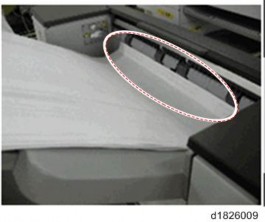
This can be solved by attaching the proof support tray on the proof tray [A].
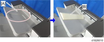
Installation
Problem that may occur after attaching this support tray:
When printing A4, LT or smaller paper with the support tray, the machine stacks only 200 sheets, which is less than the standard specification of 250 sheets.
When printing B4, LG or larger paper with the support tray, the machine stacks 50 sheets, which is the same as the standard specification.
- Remove the external orange tapes and shipping retainers.
- When installing this option, turn OFF the main power and unplug the power cord from the wall socket. If installing without turning OFF the main power, an electric shock or a malfunction may occur.
[*]PUNCH UNIT PU3050
- This Punch Unit is for the Booklet Finisher SR3220 (D3B9).
ACCESSORY CHECK
No. Description Q’ty Remarks 1 Punch unit 1 2 Cover 1 3 Stay 1 4 Hopper 1 5 Side-to-side detection unit 1
6Punch unit movement motor unit
17 Hopper guide plate 1 8 Guide plate 1 9 Tapping screws - M3 × 6 16 10 Harness (Short) 1 11 Harness (Long) 1 Not used for this machine 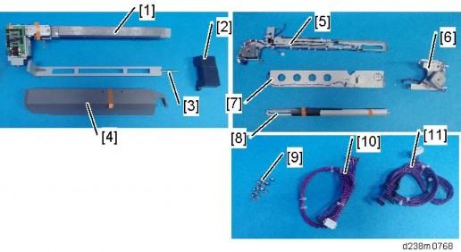
Installation
INSTALLATION PROCEDURE
- When installing this option, turn OFF the main power and unplug the power cord from the wall socket. If installing without turning OFF the main power, an electric shock or a malfunction may occur.
- Take out of the box, and remove the orange tapes and shipping retainers.
- Pull out the finisher interface cable, and move it away from the machine.
- Remove the finisher rear cover [A]
×3).

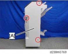
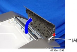
- Open the top cover, and then remove the arm [A]
×1).

- Open the finisher front cover, remove the three knobs
x1).

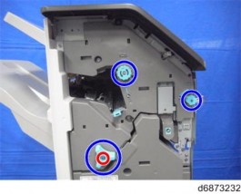
- Knobs with a lock mechanism are removed using a knob screwdriver or similar while releasing the lock.
- Knobs with a lock mechanism are removed using a knob screwdriver or similar while releasing the lock.
- Pull the saddle stitch unit [A] or stapling unit.
Remove the finisher inner cover [A] ( ×3)
7.
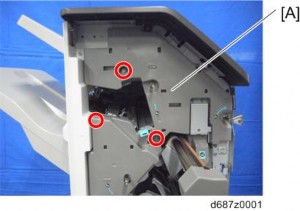
Installation
- Remove the connector at the back of the inner cover.
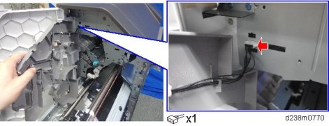
- Cut off part of the finisher inner cover [A].
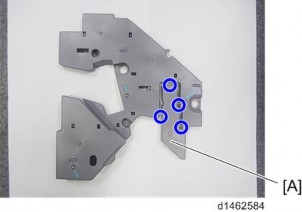
- Remove the guide plate [A]
×4).

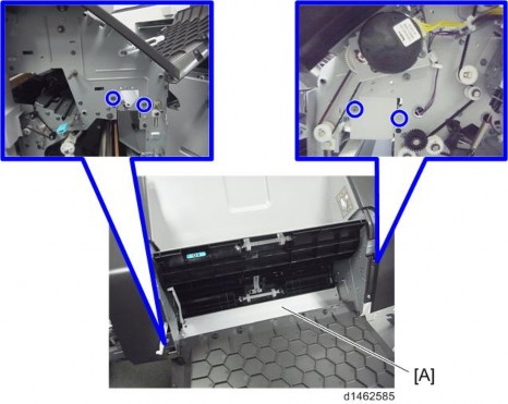
- Insert and attach the hopper guide plate [A] from the front
×4).

At this time, pass the harness through the clamp [C].
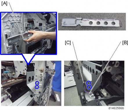
[*]Attach the stay [A]×3).

Front : Insert the holes in the stay over the embossed parts on the finisher. Rear [C]: Place the axis of the stay through the notch in the finisher.
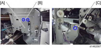
Installation
[*]Insert and attach the guide plate [A] from the rear×2).
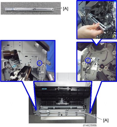
[*]Insert and attach the side-to-side detection unit [A] from the rear×2).
Front: The two shafts of the unit are passed through bearings in the finisher.
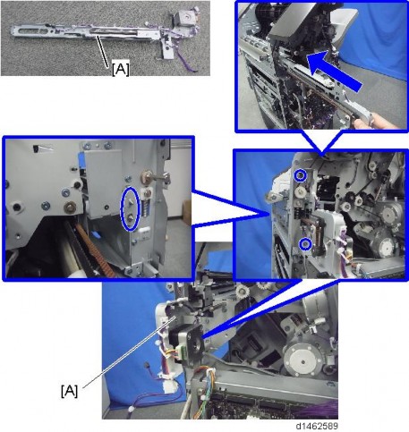
[*]Connect the harness [A] of the hopper guide plate to the relay connector of the side-to-side detection unit, and then clamp the harness.
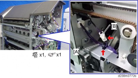
Installation
[*]Insert and attach the punch unit [A] from the rear.
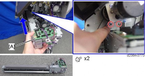
[*]Attach the punch unit movement motor unit [A] so that the gear meshes firmly×2).
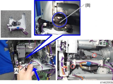
[*]Insert the hopper [A].
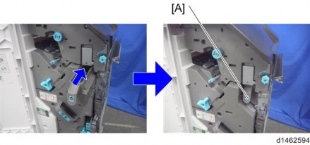
[*]Connect the provided harness to the punch unit board [A] and the control board of the finisher×6).
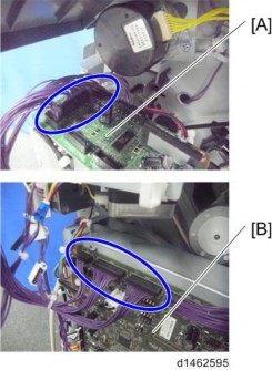
Installation
[*]Remove the harness [A] from the clamp , and connect it to the punch unit board [C]×1).
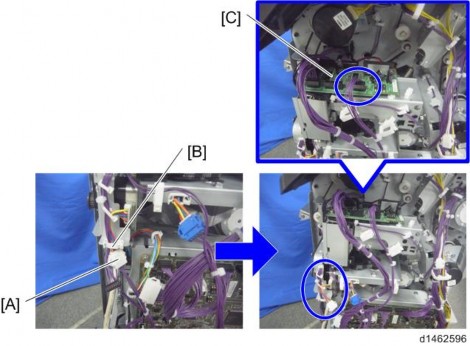
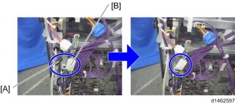
[*]Connect the harness [A] of the side-to-side detection unit to the relay connector of the harness×1).
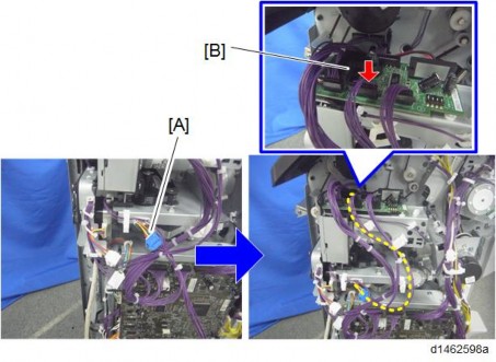
[*]Connect the harness [A] of the punch unit movement motor unit to the punch unit board×1).
[*]Attach the supplied cover [A] to the punch unit board.
[*]Clamp the harnesses.
Installation
[*]Reattach the finisher rear cover.
[*]Reattach the finisher inner cover and three knobs.
[*]Close the front cover.
[*]Close the top cover.
[*]Reconnect the finisher to the machine, and connect the interface cable.
[*]Turn ON the main power.
[*]Check that the punch can be selected at the operation panel, and check the operation.
- When installing this option, turn OFF the main power and unplug the power cord from the wall socket. If installing without turning OFF the main power, an electric shock or a malfunction may occur.
[*]INTERNAL FINISHER SR3130 (D690)
ACCESSORY CHECK
No. Description Q’ty Remarks 1 Staple Cartridge 1 2 Front Right Cover 1 3 Bottom Plate 1 4 Left Lower Cover 1
5
Entrance Guide Plate
1Not used when the punch unit is attached. 6 Stabilizer 2 7 Paper Support Guide 1 8 Driven Roller (Flat) 1 - Screw - M3 × 6 6 - Tapping Screw – M4 x 6 1 - Decal - EMC Address 1
-Notes on Installing the Optional Unit
1
Installation
INSTALLATION PROCEDURE
- When installing this option, turn OFF the main power and unplug the power cord from the wall socket. If installing without turning OFF the main power, an electric shock or a malfunction may occur.
- This option cannot be used together with the following peripherals:
- Internal Shift Tray SH3070 (D691)
- Side Tray Type M3 (D725)
- Internal Finisher SR 3180 (D766)
- Bridge Unit BU3070 (D685)
- To use together with the "1 Bin Tray BN3110 (D3CQ)", after attaching the bottom plate of this option, attach the "1 Bin Tray BN3110 (D3CQ)", and then install this option.
- To use together with the "Punch Unit PU3040 (D716)", first attach the "Punch Unit PU3040 (D716)" before installing this option.
- When installing this option, turn OFF the main power and unplug the power cord from the wall socket. If installing without turning OFF the main power, an electric shock or a malfunction may occur.
- Remove the orange tapes and shipping retainers.
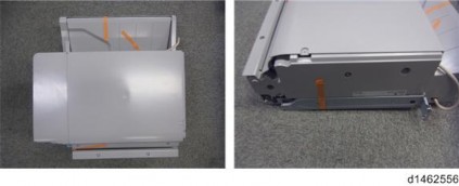
- Remove the package accessories (fixing screws, etc.).
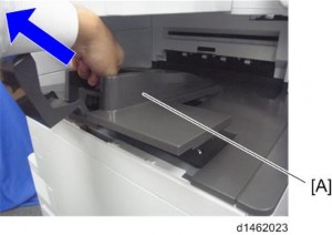
- Remove the paper exit tray [A].
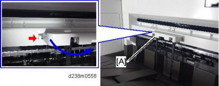
- Remove the paper exit feeler [A].
- Open the front cover, and then remove the upper left cover [A]
×1).

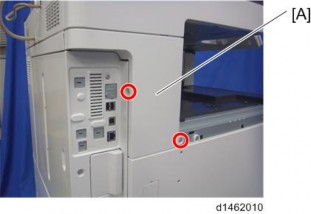
Remove the left rear cover [A] ( ×2).
6.
7. Remove the inverter tray [A], and tray support plate

