- Enter the SP mode.
- Do SP5-846-051 (Backup All Addr Book).
- Exit the SP mode, and then turn OFF the main power switch.
- Remove the SD card form the SD card slot 2 (lower).
- Install the SD slot cover.
- If the capacity of SD card is not enough to store the local user information, an error message is displayed.
- Carefully handle the SD card, which contains user information. Do not take it back to your location.
5.9.3 UPLOAD
- Turn OFF the main power.
- Remove the SD slot cover at the left rear side of the machine.
- Install the SD card, which has already been uploaded, into the SD card slot 2 (lower).
- Turn ON the main power.
- Enter the SP mode.
- Do SP5-846-052 (Restore All Addr Book).
- Exit the SP mode, and then turn OFF the main power switch.
- Remove the SD card form the SD card slot 2 (lower).
- Install the SD slot cover.
- The counter in the user code information is initialized after uploading.
- The information of an administrator and supervisor cannot be downloaded nor uploaded.
- If there is no data of address book information in the SD card, an error message is displayed.
CAPTURING THE DEVICE LOGS
OVERVIEW
With this feature, you can save device logs that are stored in the machine (HDD or operation panel) or an SD card. It allows the Customer Engineer to save and retrieve error information for analysis.
The Capturing Log feature saves device logs for the following four.- Controller device log including operation log
- Engine device log
- FCU device log
- Operation panel log
- In older models, a technician enabled the logging tool after a problem occurred. After that, when the problem had been reproduced, the technician was able to retrieve the device log.
- However, this new feature saves the device logs at the time that problems occur. Then you can copy the logs to an SD card.
- You can retrieve the device logs using a SD card without a network.
- Analysis of the device log is effective for problems caused by the software. Analysis of the device log is not valid for the selection of defective parts or problems caused by hardware.
- Make sure to shut down and reboot the machine once before retrieving the Debug Logs. Otherwise, the latest settings may not be collected when the debug logs are retrieved.
Types of device logs that can be saved
Type Storage Timing Destination (maximum storage capacity) Controller device log including operation log HDD (4 GB) or SD card connected to the service slot.
When the data gets over 4.0 GB, the older data is deleted.- Saved at all times
Type Storage Timing Destination (maximum storage capacity) Engine device log HDD or SD card connected to the service slot (Up to 300 times) FCU device log HDD or SD card connected to the service slot Operation panel log Memory in the operation panel.
- When an engine SC occurs
- When paper feeding/output stop because of a jam
- When the machine doors are opened during normal operation
- When a specified amount of FCU device log is stored in the FCU. If fax application is unavailable (e.g. not installed), the machine does not transfer the log.
- When an error related to the operation panel occurs.
System Maintenance
- Device logs are not saved in the following conditions:
- While erasing all memory
- While data encryption equipment is installed
- While changing the firmware configuration
- Forced power OFF (accidentally disconnecting the outlet)
- Engine device log while the machine is shutting down
- When the power supply to the HDD is off because of energy saving (engine OFF mode/STR mode)
- When one of the following SCs occurs: SC672, SC816, SC819, SC878, SC899, SC859, SC860, SC861, SC863, or SC864
- The following logs are not saved:
- Logs related to the energy saver mode (Engine-off, suspend-mode, or other cases) Network communication log
Logs related to NRS IP-FAX log
Access log for unauthorized users (guests) - HTTP session timeout log
- Auto log-out log
- IC card related log
- Authorization for Fax
- The default save destination is the HDD. Except when it cannot be saved to the HDD for some reason, there is no need to change from the HDD to an SD card.
- If you want to change the save destination to an SD card, do the following.
- Set SP5-858-002 (Collect Machine Info: Save To) to ”1 (SD)”
- Execute SP5-858-003 (Collect Machine Info: Make Log Trace Dir) to make a folder for the log in the SD card.
- Turn the power switch OFF and ON.
- It is recommended to use the SD card (8 GB) provided as a service part. The part number of the SD card that is registered as a service part is "B6455040".
Security of the Operation Log
The following operation logs related to security are not saved.
- User ID
- Password
- IP address
- Telephone number
- Encryption key
- Transition to SP mode
RETRIEVING THE DEVICE LOGS VIA OPERATION PANEL
- Retrieve device logs to identify the date of occurrence of the problems and to find details of the problems
- e.g.: At around 8:00 am on March 10, an engine stall occurred. The operation panel does not respond. Turn the main power supply off / on.
- Analysis of the device log is effective for problems caused by the software. Analysis of the device log is not valid for the selection of defective parts or problems caused by hardware.
Procedure for Retrieving the Device Log with SD Card- Insert the SD card into the slot on the side of the operation panel or the service slot.
- It is recommended to use the SD card (2 GBs* or 8 GBs**) provided as a service part. This is because the log data can be acquired much faster than when using commercially available SD cards.
- Format the SD card by using SD Formatter from Panasonic before copying the logs: https://www.sdcard.org/downloads/formatter_3/ (free software)
- Insert the SD card into the machine's service slot instead of the SD slot on the side of the operation panel.
* The part number of the SD card with 2 GBs that is registered as a service part is "B6455030".
** The part number of the SD card with 8 GBs that is registered as a service part is "B6455040".
- Turn ON the main power.
- Enter SP mode.
- Specify the date that the problem occurred in SP5-858-101 (Start Date) by setting it to the year-month-day calendar format.
- For example, if a problem occurred on February 1, 2015, the date should be set to "20150201", as shown above.
- Be sure to confirm the date when the problem occurred before obtaining the logs.
- Specify the number of days to collect the logs in SP5-858-102 (Days of Tracing).
- "2" is set by default, which is the minimum needed for investigating the problem.
- A value of "1" to "180" can be set.
- Execute SP5-858-111 (Acquire All Info & Logs) to copy all of the log types to an SD card.
It is possible to obtain the logs separately by the following SPs.
SP Collectable Information and/or Logs
SP5-858-111All of the information and logs that are collected by executing the SPs from SP5-858-121 to SP5-858-145, and SMC. SP5-858-121 Configuration page SP5-858-122 Font page SP5-858-123 Print settings list SP5-858-124 Print Error log SP Collectable Information and/or Logs
SP5-858-131Fax information (whether the fax destinations are included or not depends on the setting of SP5-858-103.) SP5-858-141 Controller log, engine log, operation panel log, FCU, and SMC. SP5-858-142 Controller log SP5-858-143 Engine log SP5-858-144 Operation panel log SP5-858-145 FCU log SP5-992-001 SMC
- After executing the SP for copying the information and/or logs, a confirmation screen will appear. To proceed with obtaining the information and/or logs, tap "Execute"

- The approximate time it takes to transfer the debug log is as follows. Transfer time may be affected by the type or format of the SD card.
Controller device log (GW device log): 2 - 20 minutes Engine device log: 2 minutes
Operation panel device log: 2 - 20 minutes
If the estimated time is not calculated due to an error, an error code will be displayed.
Error Code Description -1 Other. Error Code Description -2 No SD card is inserted in the service slot or in the SD slot on the side of the operation panel. In this case, insert an SD card into either of the SD slots. -3 The SD card is locked. In this case, unlock the SD card, as shown below.

[A]: Unlocked, : Locked
System Maintenance
[*]Wait for the information and/or logs to be copied to the SD card.

[*]After a message stating that the process has completed appears on the operation panel, confirm that the LED light next to the SD card slot is not flashing and then remove the SD card.
[*]Make sure that the SD card access LED is off, then remove the SD card.
- The process of obtaining logs fails in the following cases:
- When the size of the logs to obtain exceeds the amount of space available on the SD card.
- When the SD card is removed while the logs are being copied to it.
- When the SD card is not formatted.
- If ‘failed’ appears on the touch panel display, turn the power off, and then recover from step 1 again.
- The approximate time it takes to transfer the debug log is as follows. Transfer time may be affected by the type or format of the SD card.
[*]RETRIEVING THE DEVICE LOGS VIA WEB IMAGE MONITOR
The device logs can be retrieved via the Web Image Monitor.
- Access the following URL and logon as an administrator:
http://[IP address or host name]/web/entry/df/websys/direct/getSysInfo.cgi

- Specify the date that the problem occurred and the number of days to download the logs. If the fax destinations need to be included in the fax information, set "On" as "Obtain Fax Destination(s) Information". Then click "Download".

- "3" is set by default for "Number of days, including date fault occurred, to obtain". However "2", which is the minimum needed for investigating the problems, is recommended for reducing the downloading time.
- "Obtain Fax Destination(s) Information" is set to "Off" by default.
- The confirmation screen will appear and the information and/or logs will start downloading. To proceed to download the information and/or logs, wait for the open-or-save dialog to appear.

System Maintenance
- To cancel downloading, click "Cancel".
- To reconfigure some settings, click "Download again".
- Operation panel when downloading the logs:

- After a while, the open-or-save dialog will appear. Specify where to download and save the file.
- The debug logs are saved with the following file names. These names are the same as the files downloaded with SD card.
| Controller log (mmesg) | /LogTrace/[the model number]/watching/[yyyymmdd_hhmmss]_[a unique value].gz |
| Engine device log | /LogTrace/[Machine Serial]/engine/[yyyymmdd_hhmmss].gz |
| Operation panel log | /LogTrace/[the model number]/opepanel/[yyyymmdd_hhmmss].tar.gz |
SMC | /LogTrace/[the model number]/smc/[the model number]_[5992XXX]_[yyyymmdd]_[hhmmss].csv |
| Configuration page | /LogTrace/[the model number]/gps/ConfigrationPage/ConfigrationPage_ [yyyymmdd_hhmmss].csv |
Font page |
|
| Print settings list |
].csv |
| Error log | /LogTrace/[the model number]/gps/ErrorLog/[yyyymmdd_hhmmss].csv |
| Fax information | /LogTrace/[the model number]/faxreport/[yyyymmdd_hhmmss].csv |
| FCU debug log | /LogTrace/[Machine Serial]/fculog/[yyyymmdd_hhmmss].gz |
System Maintenance
SMC LIST CARD SAVE FUNCTION
OVERVIEW
SMC List Card Save
The SMC List Card Save (SP Text Mode) function is used to save the SMC list as CSV files to the SD-card inserted into the operation panel SD-card slot.
- Make sure to shut down and reboot the machine once before exporting the SMC sheet data. Otherwise, the latest settings may not be collected when the SMC is exported.
PROCEDURE
- Turn OFF the main power.
- Insert the SD card into the operation panel SD-card slot, and then turn OFF the main power.
- Enter SP mode.
- Select "System SP".

- Select SP5-992-001 (SP Text Mode).
- Select a detail SP number shown below to save data on the SD card.
SP5-992-xxx (SP Text Mode)
Detail No. SMC Categories to Save 001 All (Data List) 002 SP (Mode Data List) 003 User Program 004 Logging Data Detail No. SMC Categories to Save 005 Diagnostic Report 006 Non-Default 007 NIB Summary 008 Capture Log 021 Copier User Program 022 Scanner SP 023 Scanner User Program 024 SDK/J Summary 025 SDK/J Application Info 026 Printer SP 027 Smart Operation Panel SP 028 Smart Operation Panel UP
- Press [EXECUTE].

- Press [EXECUTE] again to start. Press [CANCEL] to cancel the saving.

System Maintenance
- "It is executing it" is shown on the screen while executing.

- Wait for 2 to 3 minutes until "Completed" is shown.
- The SMC list saving may take from 2 to 3 minutes to complete.
- Press [CANCEL] to abort executing.
- Press [Exit] to exit from SP mode.
FILE NAMES OF THE SAVED SMC LISTS
The SMC list data saved on the SD-card will be named automatically. The file naming rules are as follows.
Example:
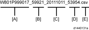
A:
Machine serial number (fixed for each machine) B:
SP number saved in this file.
First four digits (5992) in this part are fixed. The other one or two digits are the detail SP number(s). In this case, it is one digit. Therefore, this file is of SP5-992-001 (All data list). See the upper SP table for the correspondence between SP detail numbers and the contents.
C:
File creation date
Year/Month/Day ("Zero" will be omitted if each is one digit.)
D:
File creation time
Hour/Minute/Second ("Zero" will be omitted if each is one digit.)
E:
File Extension CSV (Comma Separated Value)
This part is fixed.
- A folder named by the machine serial number will be created on the SD card when this function is executed.
- This function can save the SMC list data only to an SD card inserted into the operation panel SD card slot.
ERROR MESSAGES
- Failed:
FACTOR: Read-only file system, No space left on device.
If an error occurs, pressing "Exit" will cause the device to discard the job and return to the ready state.
System Maintenance
UP/SP DATA IMPORT/EXPORT
UP DATA IMPORT/EXPORT
Data that can be imported and exported
- Copier / Document Server Features
- Printer Features
- Scanner Features
- Facsimile Features
- Browser Features
- Extended Feature Settings
- Program (Document Server)
- Program (Copier)
- Program (Scanner)
- Web Image Monitor Setting
- Web Service Settings
- System Settings
Data that cannot be imported or exported - Some System Settings *1 *2
*1 The setting for the date, settings that require the device certificate, and settings that need to be adjusted for each machine (for example, image adjustment settings) cannot be imported or exported.
*2 Settings only for executing functions and settings only for viewing cannot be imported or exported. - Extended Feature Settings
- Address book
- Programs (fax function)
- Programs (printer function)
- User stamp in Copier / Document Server Features
- Settings that can be specified via telnet
- @Remote-related data
- Counters
- EFI printer unit settings
- Settings that can only be specified via Web Image Monitor or Web Service (for example, Bonjour, SSDP setting)
Exporting Device Information
This can be exported / imported by an administrator with all privileges.
When exporting SP device information from the control panel, the data is saved on an SD card.- Insert an SD card into the media slot on the side of the control panel.
- Log in from the control panel as an administrator with all privileges.
- Press [User Tools] icon > [Machine Features] > [System Settings].
- Press [Administrator Tools].
- Press [Device Setting Information: Export (Memry Strge Devc)].

- Set the export conditions.

- Specify whether to [Include] or [Exclude] the "Device Unique Information". "Device Unique Information" includes the IP address, host name, fax number, etc.
- Specify an encryption key.
- Press [Run Export].
- Press [OK].
- Press [Exit].
- Log out.
- If data export fails, the details of the error can be viewed in the log.
- When device Information is periodically imported, it is necessary to create the device setting information file with special software and store it on the web server.
Importing Device Information
This can be exported / imported by an administrator with all privileges. Import device information saved on an SD card.- Insert an SD card into the media slot on the side of the control panel.
- Log in from the control panel as an administrator with all privileges.
- Press [User Tools] icon > [Machine Features] > [System Settings].
- Press [Administrator Tools].
- Press [Device Setting Information: Import (Memry Strge Devc)].
- Configure the import conditions.

- Press [Select] of the "Device Setting Info. File" to select the file(s) to import.
- When inserting a file into a home screen, press [Select] for the Image for Home screen and select the file. You cannot use this setting when using the Smart Operation Panel.
- Specify whether to [Include] or [Exclude] the "Device Unique Information". "Device Unique Information" includes the IP address, host name, fax number, etc.
- Enter the encryption key that was specified when the file was exported.
- Press [Run Import].
- Press [OK].
- Press [Exit].
The machine restarts.
- If data export fails, the details of the error can be viewed in the log.
SP DATA IMPORT/EXPORT
Data that can be imported and exported
- System SP
- Printer SP
- Fax SP
- Scanner SP
Exporting Device Information
When exporting SP device information from the control panel, the data is saved on an SD card.- Insert an SD card into the media slot on the side of the control panel.
- Enter SP mode.
- Press SP5-749-001 (Import/Export: Export)
- Select "Target" SP settings (System/Printer/Fax/Scanner/Smart Operation Panel) to be exported.
- Select "Option" settings (Unique/Secret).
Item Specification Note Unique Unique Unique information that can be updated information of the #1. Items that are to be used to identify the machine is machine. included in the Example: Network Information/ Host name / exported file if Information related to fax number /Mail address you select assigned to the machine "Unique" setting. #2. Items for specifying the options equipped on the machine. Example: Lot number for developer Unique information that cannot be updated #1. Items that may cause a problem if imported Example: Serial number / Information related to @Remote #2. Items for managing the history of the machine Example: Time and date / Counter information / Installation date #3. Setting values for the Engine Item Specification Note Secret Secret Secret information information is #1. Data that cannot be exported without being exported if you encrypted. select "Secret" (Exported data is encrypted.) setting. Example: Password / Encryption key / PIN code #2. Confidential information for the customer Example: User name / User ID / Department code / Mail address / Phone number #3. Personal information Example: Document name / Image data #4. Sensitive information for the customer Example: MAC address / Network parameters
System Maintenance
* The IP address is exported when both 'Unique' and 'Secret' are selected. - Select "Crpt config" setting (Encryption).
Encryption Select whether to encrypt or not when exporting.
If you push the "Encryption" key, you can export secret information.If the encryption function is used, setting of an encryption key is required by direct input. - Type the arbitrary password using the soft keyboard
- Can enter up to 32 characters
- Press [Execute].
- Press [OK].
- If data export fails, the details of the error can be viewed in the log.
- Importing Device Information
- Insert an SD card into the media slot on the side of the control panel.
- Enter SP mode.
- Press SP5-749-101(Import/Export: Import)
- Select a unique setting.
- Press [Encryption Key], if the encryption key was created when the file was exported.
- Select an encryption setting.
Unique If you want to apply the unique information to the target machine, select the "Unique" key. Refer to the above information. Encryption If an encrypted file is selected as the import file, this setting is required.
- Press [Execute].
- Press [OK].
- If data export fails, the details of the error can be viewed in the log.
POSSIBLE SOLUTIONS FOR IMPORT/EXPORT PROBLEMS
- The access log file is created when export/import is executed. The file is stored in the same location as the exported device setting information file.
The result code will appear in the circled area illustrated below.- Example of a log file

If you cannot solve the problem or do not know how to solve it after checking the code, note down the error log entry, then contact your supervisor.
Result Code Cause Solutions 2 (INVALID REQUEST) A file import was attempted between different models or machines with different device configurations. Import files exported from the same model with the same device configurations. 4 (INVALID OUTPUT DIR) Failed to write the device information to the destination device. Check whether the destination device is operating normally. 7( MODULE ERROR) An unexpected error occurred during import or export. Switch the power off and then back on, and then try the operation again. If the error persists, contact your supervisor. Result Code Cause Solutions 8 (DISK FULL) The available storage space on the external medium is insufficient. Execute the operation again after making sure there is enough storage space. 9 (DEVICE ERROR) Failed to write or read the log file. Check whether the path to the folder for storing the file or the folder in which the file is stored is missing. 10 (LOG ERROR) The hard disk is faulty. Contact your supervisor. 20 (PART FAILED) Failed to import some settings. The reason for the failure is logged in "NgCode". Check the code.
Reason for the Error (Ng-Name)
The specified value exceeds the allowable range.
The permission to edit the setting is missing.
The setting does not exist in the system.
The setting cannot be changed because of the system status or interlocking with other specified settings.
The setting cannot be changed for some other reason.21 (INVALID FILE) Failed to import the file because it is in the wrong format in the external medium. Check whether the file format is correct. The import file should be a CSV file. 22 (INVALID KEY) The encryption key is not valid. Use the correct encryption key. - INVALID VALUE
- PERMISSION ERROR
- NOT EXIST
- INTERLOCK ERROR
- OTHER ERROR
System Maintenance
- When exporting device information from the control panel, the data can be saved only on an SD card.
- The file format for exports is CSV.
CARD SAVE FUNCTION
OVERVIEW
Card Save:
- The Card Save function is used to save print jobs received by the printer on an SD card with no print output. Card Save mode is toggled using printer Bit Switch #1 bit number 4. Card Save will remain enabled until the SD card becomes full, or until all file names have been used.
- Captures are stored on the SD card in the folder /prt/cardsave. File names are assigned sequentially from PRT00000.prn to PRT99999.prn. An additional file PRT.CTL will be created. This file contains a list of all files created on the card by the card save function.
- Previously stored files on the SD card can be overwritten or left intact. Card Save SD has "Add" and "New" menu items.
- Card Save (Add): Appends files to the SD Card. Does not overwrite existing files. If the card becomes full or if all file names are used, an error will be displayed on the operation panel. Subsequent jobs will not be stored.
- Card Save (New): Overwrites files in the card's /prt/cardsave directory.
Limitation:
- Card Save cannot be used with PJL Status Readback commands. PJL Status Readbacks will not work. In addition they will cause the Card Save to fail.
PROCEDURE
- Turn OFF the main power.
- Insert the SD card into slot 2 (lower), then turn ON the main power.
- Enter SP mode.
- Select the "Printer SP".
- Select SP-1001 "Bit Switch".
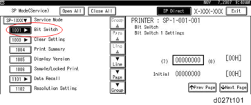
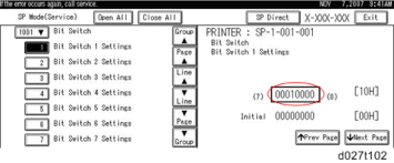
- Select "Bit Switch 1 Settings" and use the numeric keypad to turn bit 4 ON and then press the "#" to register the change. The result should look like: 00010000. By doing this, Card Save option will appear in the "List/Test Print" menu.
System Maintenance
- Press "Exit" to exit SP Mode.
- Press the "User Tools" icon > "Machine Features".
- Select "Printer Features".
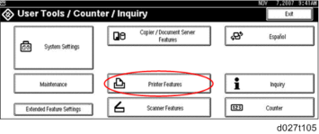
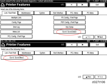
- Card Save (Add) and Card Save (New) should be displayed on the screen. Select Card Save (Add) or Card Save (New).
- Press "OK" and then return to Home screen.
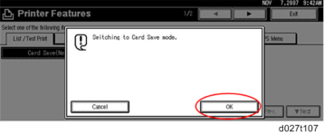
- Press the "Printer (Classic)" icon.

- "Hex Dump Mode" is be displayed in the top left of the display panel.

- Send a job to the printer. The Communicating light should start blinking.
- As soon as the printer receives the data, it will be stored on the SD card automatically with no print output.
Nothing is displayed on the screen, indicating that a Card Save operation was successful. - Press "Reset" to exit Card Save mode.

- Change the Bit Switch Settings back to the default 00000000, then press the "#" in the numeric keypad to register the changes.
- Remove the SD card after the main power switch is turned OFF.
ERROR MESSAGES
- Card Save error messages:
- Init error: A card save process (e.g. card detection, change to kernel mode) failed to initialize.
- Card not found: Card cannot be detected in the slot.
- No memory: Insufficient working memory to process the job.
- Write error: Failed to write to the card.
- Other error: An unknown error occurred.
If an error occurs, pressing "OK" will cause the device to discard the job and return to the ready state.
System Maintenance
TROUBLESHOOTING
RE V IS ION H IST ORY Page Date Added/ Updated/ New None
Troubleshooting
TROUBLESHOOTING
SELF-DIAGNOSTIC MODE
SC AUTOMATIC REBOOT
When an ordinary SC (pattern D) is generated, automatically reboot is performed. Automatic reboot or reboot by user operation can be set by SP5-875-001 (SC automatic reboot setting out) (default value: 0 "Automatic reboot").
When a type D occurs, automatic reboot is done or the machine display asks the customer if it can reboot. However, when the SC occurs twice in a short time, the machine sends a report to the
@Remote server without rebooting. This is because just rebooting may not be a good solution if an SC occurs twice.
When an automatic reboot is performed, a confirmation screen is displayed after reboot. The confirmation screen can be cancelled by pressing the [OK] key (display is not cancelled only when the main power switch is switched OFF to ON).
Screen display during reboot- Status display on the current screen
- Post-processing ...... Post-processing during printing, etc.
- Automatic reboot .... After operation end Post-processing

Until automatic reboot

- Reset key (Reboot key) Key to perform reboot
# Cancel key is not displayed. - Turn on spanner LED (same as when an SC is generated).
Operation during SC reboot - Timing of SC reboot
When @Remote is enabled, and when a NRS alarm*1 is not generated, the corresponding SC is the object of an automatic reboot.
*1 NRS alarm: Issued when an ordinary SC (type D) is generated twice while the total counter counts 10 times. - Time to automatic reboot
Reboot is performed 30 seconds after an engine reboot is possible, after the end of post-processing during printing, etc.
At that time, a reboot is performed even if the MFP is operating. The engine does not start process control when a reboot is possible. - Automatic reboot
See the flowchart below.
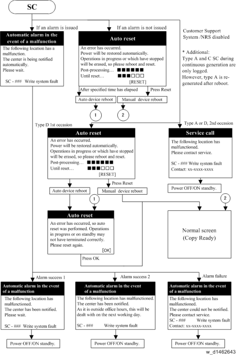
- For the SC list of automatic reboot, refer to page 6-10 "List of Automatic Reboot Target SC".
Troubleshooting
- Status display on the current screen
CONTROLLER SELF-DIAGNOSIS OUTLINE
Controller self-diagnosis includes 3 types, i.e., "ordinary self-diagnosis", "detailed self-diagnosis", and "SC detection". "Ordinary self-diagnosis" is diagnosis performed for every power ON, and "detailed self-diagnosis" is diagnosis treated as part of the service tools. "SC detection" detects mechanical faults when power is switched on or when the machine is operating.
Detailed self-diagnosis – Method- After attaching the option "IEEE 1284 board" to the controller board, connect the provided conversion connector.
- Set a loop back connector in the reference Centronics I/F.
- Press the main power supply switch while simultaneously pressing the "#" and "./* key. The display changes to the following screen, and self-diagnosis starts.

- After the end of detailed self-diagnosis, a "Self-diagnosis results report" is automatically printed.
- If a Centronics loopback connector is not fitted, a Centronics diagnosis error (SC 835) is generated.
CONTROLLER SELF-DIAGNOSIS FLOWCHART
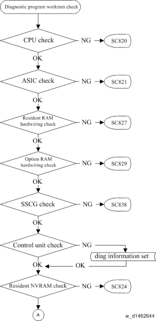
Troubleshooting
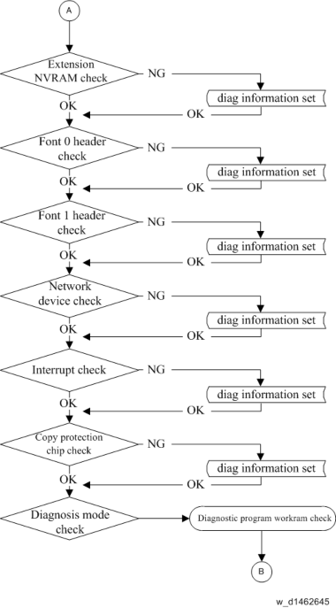
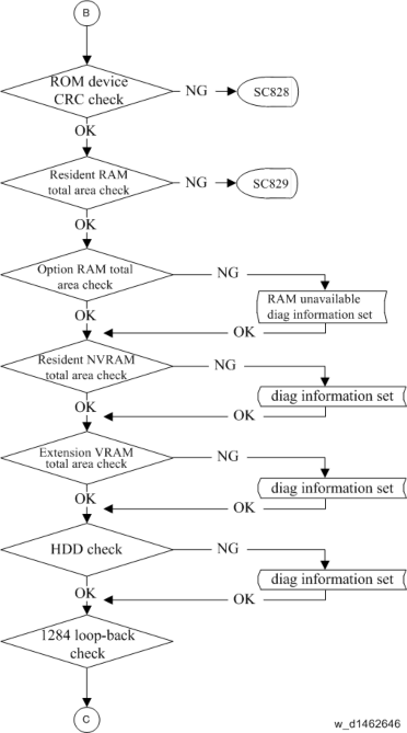
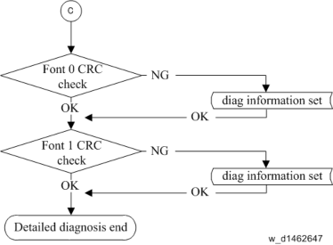
Troubleshooting
HDD-RELATED MESSAGE
When an error occurs to the HDD, the HDD abnormality message appears on the operation panel and the screen for formatting is displayed. Also when replacing the HDD, a message "Hard Disk is replaced." appears on the operation panel and the screen for formatting is displayed.
Refer to the table shown below for the conditions of the message display.
Even when replacing the controller board, a banner "Hard Disk is replaced." appears. It is because the machine recognizes HDD has been replaced when the controller board that does not hold the HDD identification information is attached.
Message list
MessageDisplay Type Normal/ Abnormal Error Condition/ Major Cause/ Solution
SC870
banner
abnormalThe HDD cannot be accessed at power-on. NVRAM defective Turn the main power off/on to initialize the machine.
*When replacing the NVRAM, if possible, back up the address book before replacing the NVRAM and restore it after replacing the NVRAM.
MessageDisplay Type Normal/ Abnormal Error Condition/ Major Cause/ Solution
Hard Disk will be formatted due to problem with Hard Disk.
pop-up formatting button
abnormalManagement file on the HDD can not be read. Or the file system can not be mounted. HDD defective Replace the HDD.
Problem with the Encryption Key for Hard Disk. Format Hard Disk.
pop-up formatting button
abnormalThe encryption key for the HDD is abnormal. HDD defective Replace the HDD.
Hard Disk is replaced. Format Hard Disk.
pop-up formatting button
normalA new HDD is attached. A new HDD attached Push the formatting button.
Hard Disk is replaced.
banner
abnormalThe HDD is replaced (Data can be read). Turn the main power off/on. Formatting Hard Disk... Please wait, also make sure the main power switch is not turned off.
pop-up
abnormalPushing the formatting button. Formatting the HDD -
Hard Disk is formatted. Turn main power switch off then on.
pop-up
abnormalFormatting the HDD is finished. Formatting the HDD Turn the main power off/on. - Controller board replaced
- After starting the machine without an HDD, a new HDD is attached to the machine and then restart the machine.
SERVICE CALL CONDITIONS
SUMMARY
The ‘SC Table’ section shows the SC codes for controller errors and other errors. The latter are put into four types. The type is determined by their reset procedures. The table shows the classification of the SC codes.
Type Display How to reset
AThe SC is immediately displayed on the operation panel when SC occurs.
The error involves the fusing unit. The machine operation is disabled. The user cannot reset the error.
Reset the SC (set
SP5-810-1) and then cycle the main power off and on.
BWhen a function is selected, the SC is displayed on the operation panel.
The machine cannot be used (down-time mitigation).
Turn the operation switch off and on.
CNo display on the operation panel. The machine operates as usual. Only the SC history is updated.
DThe SC is displayed on the operation panel.
The machine cannot be used (machine-error SC).Turn the main n power switch off and on. - When canceling a fusing unit SC, (SC544-00/ SC554-00/ SC564-00/ SC574-00), perform part replacement in accordance with the above procedure.
- When an ordinary SC (type D) is generated, an automatic reboot is performed. When an event is reported by the customer support system, even in the event of an ordinary SC, reboot is not performed. During automatic reboot, a confirmation screen is displayed after the reboot.
- When automatic reboot occurs twice continuously, an SC is displayed without rebooting, and logging count is performed. Also, when an SMC print is output, an * mark is added alongside the SC number for clarity.
- Automatic reboot can be enabled or disabled with SP5-875-001 (SC automatic reboot setting) (default value: ON).
SP descriptions
- When canceling a fusing unit SC, (SC544-00/ SC554-00/ SC564-00/ SC574-00), perform part replacement in accordance with the above procedure.
- SP5-875-001 (SC automatic reboot: Reboot Setting)
0: The machine reboots automatically when the machine issues an SC error and logs the SC error code. If the same SC occurs again, the machine does not reboot.
1: The machine does not reboot when an SC error occurs. The reboot is not executed for the pattern A or C.
SC Logging
When an SC is generated, the "total count value when the SC is generated" and the "SC code" are logged. However, if the total count value during the SC is the same as last time, logging is not performed.
Logged data can be checked by outputting an administrative report (SMC print). The SC history is logged up to the last 10 entries, and if there are more than 10 entries, data are progressively deleted starting from the oldest.
LIST OF AUTOMATIC REBOOT TARGET SC
Engine SC
Automatic reboot target SC is as follows. For details of Automatic reboot, refer to page 6-1 "SC Automatic Reboot".
| SC code | Name |
| 101-01 | Lamp Error (Scanning) |
| 101-02 | Lamp Error (LED illumination adjustment) |
| 102-00 | LED Illumination Adjustment Error |
| 120-00 | Scanner Home Position Error 1 |
| 121-00 | Scanner Home Position Error 2 |
| 141-00 | Black level detection error |
| 142-00 | White level detection error |
| 144-00 | SBU Communication Error |
| 151-00 | Black Level Error: Side 2 |
| SC code | Name |
| 152-00 | White Level Error: Side 2 |
| 154-00 | Scanner Communication Error: Side 2 |
| 161-02 | IPU error (Lsync Error: Side 2) |
| 161-20 | IPU error (DRAM initialization failure) |
| 202-00 | Polygon Motor: ON Timeout Error |
| 203-00 | Polygon Motor: OFF Timeout Error |
| 204-00 | Polygon Motor: XSCRDY Signal Error |
| 220-01 | Leading Edge: LD1 synchronization detection error: Bk |
| 220-04 | Leading Edge: LD1 synchronization detection error: Ye |
| 230-01 | FGATE ON error: Bk |
| 230-02 | FGATE ON error: Cy |
| 230-03 | FGATE ON error: Ma |
| 230-04 | FGATE ON error: Ye |
| 231-01 | FGATE OFF error: Bk |
| 231-02 | FGATE OFF error: Cy |
| 231-03 | FGATE OFF error: Ma |
| 231-04 | FGATE OFF error: Ye |
| 240-01 | LD error: Bk |
| 240-02 | LD error: Cy |
| 240-03 | LD error: Ma |
| 240-04 | LD error: Ye |
| 272-01 | LD driver communication error: Bk |
| 272-02 | LD driver communication error: Cy |
| 272-03 | LD driver communication error: Ma |
| 272-04 | LD driver communication error: Ye |
| SC code | Name |
| 272-10 | LD driver communication error: Other |
| 312-01 | Charge Roller HVP_CB Output Error (K) |
| 312-02 | Charge Roller HVP_CB Output Error (C) |
| 312-03 | Charge Roller HVP_CB Output Error (M) |
| 312-04 | Charge Roller HVP_CB Output Error (Y) |
| 324-05 | Development motor: CMY: Lock |
| 360-01 | TD sensor adjustment error (K) |
| 360-02 | TD sensor adjustment error (C) |
| 360-03 | TD sensor adjustment error (M) |
| 360-04 | TD sensor adjustment error (Y) |
| 396-05 | Drum motor (CMY) Lock |
| 441-00 | Drum transfer motor: Lock |
| 442-00 | ITB Lift Error |
| 452-00 | Paper transfer contact motor error |
| 491-00 | High voltage power source: charge/development: output error |
| 531-01 | Development Intake Fan/Right Lock |
| 531-03 | Drive Cooling Fan Lock |
| 533-03 | PSU Cooling Fan Lock |
| 533-04 | Controller Box Cooling Fan Lock |
| 534-01 | Main Exhaust Fan Lock |
| 534-02 | Toner Supply Cooling Fan Lock |
| 534-03 | Ozone Exhaust Fan Lock |
| 535-00 | Paper Exit Cooling Fan Lock |
| 540-00 | Fusing Motor: Lock |
| 542-05 | Thermopile (Center) does not reload (Low Power) |
| SC code | Name |
| 542-06 | Thermopile (Center) does not reload (Low Power) |
| 545-05 | Fusing Central Lamp Continuously Heat (Low Power) |
| 547-01 | Zero cross error (relay-contact soldering) |
| 547-02 | Zero cross error (relay contact error) |
| 547-03 | Zero cross error (low-frequency error) |
| 552-05 | Thermopile (Center) Does Not Reload (Low Power) |
| 552-06 | Thermopile (Center) Does Not Reload (Low Power) |
| 561-05 | Pressure Roller Thermistor (Center) Disconnection (Low Power) |
| 562-05 | Pressure Roller Thermistor (Center) Does Not Reload (Low Power) |
| 569-00 | Paper Exit/ Pressure Release Motor Error Detection |
| 571-05 | Pressure Roller Thermistor (Edge) Disconnection |
| 572-05 | Pressure Roller Thermistor (Edge) Does Not Reload ( Low Power) |
| 581-05 | Pressure Roller Thermistor (Full-Bleed Edge) Disconnection (Low Power) |
| 582-05 | Pressure Roller Thermistor (Full-Bleed Edge) Does Not Reload (Low Power) |
| 620-01 | ADF Communication error 1 |
| 620-02 | ADF Communication error 2 |
| 620-03 | ADF Communication error 3 |
| 621-00 | Finisher communication error |
| 622-01 | Paper bank 1 communication error for Paper Feed Unit PB3150 (D694) |
| 622-11 | Paper bank 1 communication error for Paper Feed Unit PB3220/PB3210 (D787) |
| 663-01 | Reset Detection: Imaging IOB: Software hangup occurs |
| 663-02 | Reset Detection: Imaging IOB: Power ON reset occurs |
| 663-03 | Reset Detection: Imaging IOB: Software reset occurs |
| SC code | Name |
| 663-11 | Reset Detection: Paper Transport IOB: Software hangup occurs |
| 663-12 | Reset Detection: Paper Transport IOB: Power ON reset occurs |
| 663-13 | Reset Detection: Paper Transport IOB: Software reset occurs |
| 664-01 | VODKA1 (Paper Transport Vodka) access permission error to VODKA SRAM |
| 669-01 | EEPROM OPEN: ID error |
| 669-02 | EEPROM OPEN: Channel error |
| 669-03 | EEPROM OPEN: Device error |
| 669-04 | EEPROM OPEN: Communication abort error |
| 669-05 | EEPROM OPEN: Communication timeout error |
| 669-06 | EEPROM OPEN: Operation stopped error |
| 669-07 | EEPROM OPEN: Buffer full |
| 669-08 | EEPROM OPEN: No error code |
| 669-09 | EEPROM CLOSE: ID error |
| 669-10 | EEPROM CLOSE: No error code |
| 669-11 | EEPROM Data write: ID error |
| 669-12 | EEPROM Data write: Channel error |
| 669-13 | EEPROM Data write: Device error |
| 669-14 | EEPROM Data write: Communication abort error |
| 669-15 | EEPROM Data write: Communication timeout error |
| 669-16 | EEPROM Data write: Operation stopped error |
| 669-17 | EEPROM Data write: Buffer full |
| 669-18 | EEPROM Data write: No error code |
| 669-19 | EEPROM Data read: ID error |
| 669-20 | EEPROM Data read: Channel error |
| SC code | Name |
| 669-21 | EEPROM Data read: Device error |
| 669-22 | EEPROM Data read: Communication abort error |
| 669-23 | EEPROM Data read: Communication timeout error |
| 669-24 | EEPROM Data read: Operation stopped error |
| 669-25 | EEPROM Data read: Buffer full |
| 669-26 | EEPROM Data read: No error code |
| 669-36 | Verification error |
| 669-37 | Error Detection |
| 681-01 | Toner bottle: IDChip Communication error: Invalid device ID :K |
| 681-02 | Toner bottle: IDChip Communication error: Invalid device ID :M |
| 681-03 | Toner bottle: IDChip Communication error: Invalid device ID :C |
| 681-04 | Toner bottle: IDChip Communication error: Invalid device ID :Y |
| 681-06 | Toner bottle: IDChip Communication error: Channel error :K |
| 681-07 | Toner bottle: IDChip Communication error: Channel error :M |
| 681-08 | Toner bottle: IDChip Communication error: Channel error :C |
| 681-09 | Toner bottle: IDChip Communication error: Channel error :Y |
| 681-11 | Toner bottle: IDChip Communication error: Device Error :K |
| 681-12 | Toner bottle: IDChip Communication error: Device Error :M |
| 681-13 | Toner bottle: IDChip Communication error: Device Error :C |
| 681-14 | Toner bottle: IDChip Communication error: Device Error :Y |
| 681-16 | Toner bottle: IDChip Communication error: Communication error (interrupted) :K |
| 681-17 | Toner bottle: IDChip Communication error: Communication error (interrupted) :M |
| 681-18 | Toner bottle: IDChip Communication error: Communication error (interrupted) :C |
| SC code | Name |
| 681-19 | Toner bottle: IDChip Communication error: Communication error (interrupted) :Y |
| 681-21 | Toner bottle: IDChip Communication error: Communication timeout :K |
| 681-22 | Toner bottle: IDChip Communication error: Communication timeout :M |
| 681-23 | Toner bottle: IDChip Communication error: Communication timeout :C |
| 681-24 | Toner bottle: IDChip Communication error: Communication timeout :Y |
| 681-26 | Toner bottle: IDChip Communication error: Device stops (logically) :K |
| 681-27 | Toner bottle: IDChip Communication error: Device stops (logically) :M |
| 681-28 | Toner bottle: IDChip Communication error: Device stops (logically) :C |
| 681-29 | Toner bottle: IDChip Communication error: Device stops (logically) :Y |
| 681-31 | Toner bottle: IDChip Communication error: Full of buffer (request) :K |
| 681-32 | Toner bottle: IDChip Communication error: Full of buffer (request) :M |
| 681-33 | Toner bottle: IDChip Communication error: Full of buffer (request) :C |
| 681-34 | Toner bottle: IDChip Communication error: Full of buffer (request) :Y |
| 681-36 | Toner bottle: IDChip Communication error: Verification error:K |
| 681-37 | Toner bottle: IDChip Communication error: Verification error:M |
| 681-38 | Toner bottle: IDChip Communication error: Verification error:C |
| 681-39 | Toner bottle: IDChip Communication error: Verification error:Y |
| 682-01 | TD sensor communication error: Invalid device ID :K |
| 682-02 | TD sensor communication error: Invalid device ID :M |
| 682-03 | TD sensor communication error: Invalid device ID :C |
| 682-04 | TD sensor communication error: Invalid device ID :Y |
| 682-06 | TD sensor communication error: Channel error :K |
| 682-07 | TD sensor communication error: Channel error :M |
| 682-08 | TD sensor communication error: Channel error :C |
| SC code | Name |
| 682-09 | TD sensor communication error: Channel error :Y |
| 682-11 | TD sensor communication error: Device Error :K |
| 682-12 | TD sensor communication error: Device Error :M |
| 682-13 | TD sensor communication error: Device Error :C |
| 682-14 | TD sensor communication error: Device Error :Y |
| 682-16 | TD sensor communication error: Communication error (interrupted) :K |
| 682-17 | TD sensor communication error: Communication error (interrupted) :M |
| 682-18 | TD sensor communication error: Communication error (interrupted) :C |
| 682-19 | TD sensor communication error: Communication error (interrupted) :Y |
| 682-21 | TD sensor communication error: Communication timeout :K |
| 682-22 | TD sensor communication error: Communication timeout :M |
| 682-23 | TD sensor communication error: Communication timeout :C |
| 682-24 | TD sensor communication error: Communication timeout :Y |
| 682-26 | TD sensor communication error: Device stops (logically) :K |
| 682-27 | TD sensor communication error: Device stops (logically) :M |
| 682-28 | TD sensor communication error: Device stops (logically) :C |
| 682-29 | TD sensor communication error: Device stops (logically) :Y |
| 682-31 | TD sensor communication error: Full of buffer (request) :K |
| 682-32 | TD sensor communication error: Full of buffer (request) :M |
| 682-33 | TD sensor communication error: Full of buffer (request) :C |
| 682-34 | TD sensor communication error: Full of buffer (request) :Y |
| 682-36 | TD sensor communication error: Verification error:K |
| 682-37 | TD sensor communication error: Verification error:M |
| 682-38 | TD sensor communication error: Verification error:C |
| 682-39 | TD sensor communication error: Verification error:Y |
| SC code | Name |
| 687-00 | PER Not Received Error |
| 700-01 | SPDF: Base Plate Lift Motor Error |
| 700-02 | SPDF: Original Pick-up Error |
| 700-04 | SPDF: Paper Feed Motor Error |
| 700-05 | SPDF: Pullout Motor Error |
| 700-06 | SPDF: Intermediate Motor Error |
| 700-07 | SPDF: Scanning Motor Error |
| 700-09 | SPDF: Paper Exit Motor Error |
| 701-03 | SPDF: Paper Feed Motor Driver Error |
| 701-08 | SPDF: Paper Exit Motor Driver Error |
| 702-01 | ARDF: Protection Device Intercept Error 1 |
| 702-02 | ARDF: Protection Device Intercept Error 2 |
| 702-03 | ARDF: Protection Device Intercept Error 3 |
| 702-04 | SPDF: Protection Device Intercept Error 4 |
| 702-05 | SPDF: Protection Device Intercept Error 5 |
| 780-01 | Bank 1 (Upper optional paper tray) Protection Device Intercept Error |
| 781-01 | Bank 2 (Lower optional paper tray) Protection Device Intercept Error |
| 791-00 | No bridge unit when finisher is present |
| 995-01 | CPM setting error 1 |
| 995-02 | CPM setting error 2 |
| 995-03 | CPM setting error 3 |
| 995-04 | CPM setting error 4 |
Troubleshooting
Controller SC
Automatic reboot target SC is as follows. For details of Automatic reboot, refer to page 6-1 "SC Automatic Reboot".
| SC code | Name |
| 632-00 | Counter device error 1 |
| 633-00 | Counter device error 2 |
| 634-00 | Counter device error 3 |
| 635-00 | Counter device error 4 |
| 636-01 | IC Card Error (Expanded authentication module error) |
| 636-02 | IC Card Error (Version error) |
| 637-01 | Tracking Information Notification Error (Tracking application error) |
| 637-02 | Tracking Information Notification Error (Management server error) |
| 641-00 | Communication error between BCU and Controller board |
| 641-01 | Communication error between BCU and Controller board: Timout |
| 641-02 | Communication error between BCU and Controller board: retry over |
| 641-03 | Communication error between BCU and Controller board: download error |
| 641-04 | Communication error between BCU and Controller board: UART error |
| 670-01 | Engine does not start up during the staring up |
| 670-02 | Engine does not start up after the staring up |
| 670-03 | IPU power does not start up |
| 670-04 | Communication is not linked up |
| 816-00 | Energy save I/O subsystem error |
| 816-01 | Subsystem error |
| 816-02 | Sysarch (LPUX_GET_PORT_INFO) error |
| 816-03 | Transition to STR was denied. |
| SC code | Name |
| 816-04 | Interrupt in kernel communication driver |
| 816-05 | Preparation for transition to STR failed. |
| 816-07 | Sysarch (LPUX_GET_PORT_INFO) error |
| 816-08 | Sysarch (LPUX_ENGINE_TIMERCTRL) error |
| 816-09 | Sysarch (LPUX_RETURN_FACTOR_STR) error |
| 816-10 to 12 | Sysarch (LPUX_GET_PORT_INFO) error |
| 816-13 | open() error |
| 816-14 | Memory address error |
| 816-15 to 18 | open() error |
| 816-19 | Double open() error |
| 816-20 | open() error |
| 816-22 | Parameter error |
| 816-23 | read() error |
| 816-24 | read() error |
| 816-25 | write () error |
| 816-26 | write() communication retry error |
| 816-27 | write() communication retry error |
| 816-28 | write() communication retry error |
| 816-29 | read() communication retry error |
| 816-30 | read() communication retry error |
| 816-35 | read() error |
| 816-36 to 94 | Subsystem error |
| 818-00 | Watchdog timer error |
| 821-00 | Self-diagnostics error: ASIC |
| 823-00 | Self-diagnostics error: NIC |
