HOME PAGE | < Previous | Contents | Next >
2.1 FCU
2.1.1 SRAM DATA TRANSFER PROCEDURE
When you replace the FCU board, transfer the SRAM data from the old FCU board to the new FCU board. Do the following procedure to back up the SRAM data.
![]()
The following data can be transfered: TTI, RTI, CSI, Fax bit switch settings, RAM address settings, NCU parameter settings
For D148/D149/D150 models
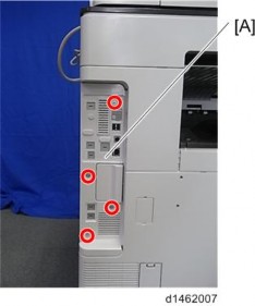
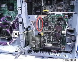
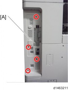
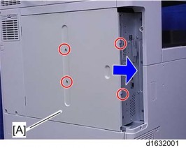
1. Remove the controller box cover [A] ![]() x 4).
x 4).
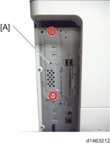
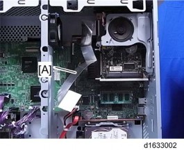
2. Remove the rear cover [A] ![]() x 4).
x 4).
3.
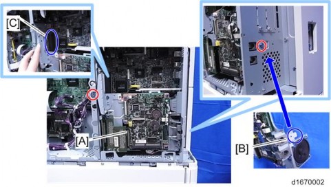
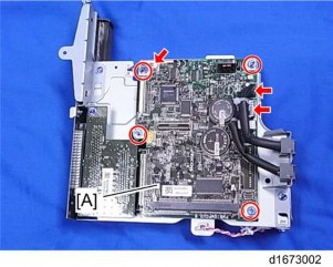
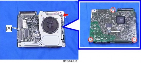
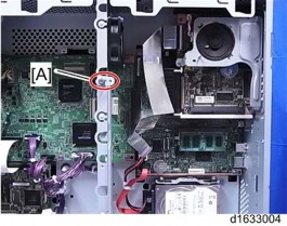
4. Replace the installed FCU board [A] with a new FCU board ![]() x 4,
x 4, ![]() x 3).
x 3).
5. Reinstall the new fax unit ![]() x 2).
x 2).
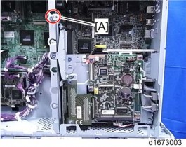
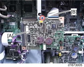
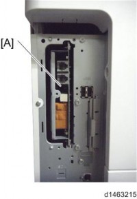
6. Attach the bracket [A] provided with the new fax unit to the center frame of the controller box ![]() x 1).
x 1).
7. Attach the flat cable [A] to CN603 of the new fax unit.
Make sure that the blue tape of the flat cable faces outward.
8. Attach the FCU board removed in step 4 to the bracket. Then attach the flat cable to CN603 of the removed FCU board ![]() x 1).
x 1).
Make sure that the blue tape of the flat cable faces outward.
![]()
The removed FCU board must be away from the metal frames. Otherwise, the removed FCU board may get a short circuit.
9. Turn on the main power switch.
10. SRAM data transmission starts. When the transmission is completed, you will hear a beeper sound.
![]()
The beeper sound is the same volume as the speaker sound.
The beeper sounds even if the sperker sound is turned off.
If the beeper does not sound, turn the main power switch on and off repeatedly and do the transmission procedure 2 or 3 times.
If the beeper does not sound after turning the main switch on and off 3 times, you need to input the settings stored in SRAM memory manually.
11. When “Ready” appears on the copy display, turn off the main power switch, and then disconnect the flat cable from the removed FCU board.
12. Remove the removed FCU board ![]() x 1).
x 1).
13. Remove the bracket from the center frame of the controller box ![]() x 1).
x 1).
14. Disconnect the flat cable from the new FCU board.
15. Re-assemble the machine.
16. Turn on the main power switch, then do SP6-101 to print the system parameter list.
17. Check the system parameter list to make sure that the data is transferred correctly.
18. Set the correct date and time with the User Tools: User Tools > System Settings > Timer Setting > Set Date/Time.
![]()
If any of the SRAM data was not transferred, input those settings manually.
For D146/D147 models
1. Remove the controller box cover [A] ![]() x 4).
x 4).
2. Remove the interface slot cover [A] ![]() x 2).
x 2).
3. Pull out the FCU [A] from the interface slot.
4. Replace the installed FCU board [A] with a new FCU board ![]() x 1, stepped screw x 2,
x 1, stepped screw x 2, ![]() x 1).
x 1).
5. Reinstall the new fax unit, and then the slot cover ![]() x 2).
x 2).
6. Remove the rear cover [A] ![]() x 4).
x 4).
7. Attach the flat cable [A] to CN603 of the new fax unit.
Make sure that the blue tapes of the flat cable face outward.
8. Attach the bracket [A] provided with the new fax unit to the center frame of the controller box ![]() x 1).
x 1).
9. Attach the FCU board removed in step 4 to the bracket. Then attach the flat cable to CN603 of the removed FCU board ![]() x 1).
x 1).
Make sure that the blue tape of the flat cable faces outward.
The removed FCU board must be away from the metal frames. Otherwise, the removed FCU board may get a short circuit.
10. Turn on the main power switch.
11. SRAM data transmission starts. When the transmission is completed, you will hear a beeper sound.
![]()
The beeper sound is the same volume as the speaker sound.
The beeper sounds even if the sperker sound is turned off.
If the beeper does not sound, turn the main power switch on and off repeatedly and do the transmission procedure 2 or 3 times.
If the beeper does not sound after turning the main switch on and off 3 times, you need to input the settings stored in SRAM memory manually.
12. When “Ready” appears on the copy display, turn off the main power switch, and then disconnect the flat cable from the removed FCU board.
13. Remove the removed FCU board ![]() x 1).
x 1).
14. Remove the bracket from the center frame of the controller box ![]() x 1).
x 1).
15. Disconnect the flat cable from the new FCU board.
16. Re-assemble the machine.
17. Turn on the main power switch, then do SP6-101 to print the system parameter list.
18. Check the system parameter list to make sure that the data is transferred correctly.
19. Set the correct date and time with the User Tools: User Tools > System Settings > Timer Setting > Set Date/Time.