HOME PAGE | < Previous | Contents | Next >
![]()
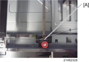
Do not touch the mirror and the lamp.
When you move the carriage, hold the central part and move it gently.
Replacement and Adjustment
Replacement and Adjustment
Replacement and Adjustment
Scanner wire assembly (front side)
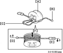
1. Pull the scanner wire ball end [B] to the pulley [A] from the left side of the pulley as shown in the diagram.
2. Set the ball [C] in the center part of the wire on the pulley.
3. Turn the ball end [D] 5 times counterclockwise along the edge on the rear side of the pulley.
4. Turn the ring end [E] 3.5times clockwise along the edge at the front side of pulley.
5. Check that the blue marks [F] of the wire overlap, and secure it temporarily with Teflon tape, etc.
Scanner Unit
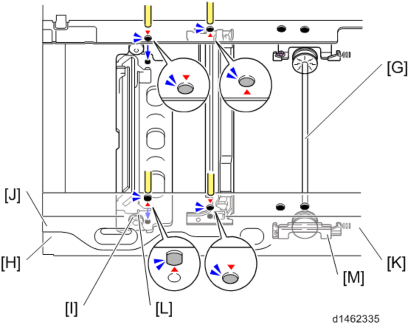
6. Set the pulley on the drive shaft [G] (tighten the screw temporarily).
7. Set the ball end of the wire in the following order.
1. Left frame pulley (outside) [H]
2. 2nd scanner carriage (outside) [I]
3. Left frame slit [J]
8. Set the ring end of the wire in the following order.
1. Right frame pulley (outside) [K]
1. 2nd scanner carriage (inside) [L]
2. Scanner retaining bracket [M]
(Tighten the screw of the scanner retaining bracket temporarily)
9. Remove the tape which temporarily held the wire in Step 5.
10. Attach the spring.