HOME PAGE | < Previous | Contents | Next >
Imageable Area Extension Unit Type M3
2.30 IMAGEABLE AREA EXTENSION UNIT TYPE M3
2.30.1 ACCESSORY CHECK
Description | Q’ty |
Paper transfer roller (Extended) | 1 |
2.30.2 INSTALLATION PROCEDURE
![]()
Do not touch the roller surface during replacement.
1. Check the Engine firmware. If the version is earlier than 1.22, then you must input all the SPs in the following table. If the version is 1.22 or later, then you only need to do SP2-400-001.
SP | Description | Default | Setting |
SP2-400-001 | Paper Transfer Roller Settings Width of Paper Transfer Roller | 0 | 1 |
SP3-232-040 | Vtref Correct:Pixel Initial ProCon Thresh | 100 | 10 |
SP3-232-041 | Vtref Correct:Pixel High Coverage Thresh:H | 100 | 60 |
SP3-232-050 | Vtref Correct:Pixel ProCon Thresh | 100 | 50 |
SP3-234-011 | Vtref Corr :Disp/Set Corr Amt(+):K | 0 | 0.05 |
SP3-234-012 | Vtref Corr :Disp/Set Corr Amt(+):C | 0 | 0.05 |
SP3-234-013 | Vtref Corr :Disp/Set Corr Amt(+):M | 0 | 0.05 |
SP3-234-014 | Vtref Corr :Disp/Set Corr Amt(+):Y | 0 | 0.05 |
SP3-234-021 | Vtref Corr :Disp/Set Corr Amt(-):K | 0 | 0.05 |
SP3-234-022 | Vtref Corr :Disp/Set Corr Amt(-):C | 0 | 0.05 |
SP3-234-023 | Vtref Corr :Disp/Set Corr Amt(-):M | 0 | 0.05 |
SP3-234-024 | Vtref Corr :Disp/Set Corr Amt(-):Y | 0 | 0.05 |
SP3-533-003 | Interrupt ProCon :Set Corr(Short):BW | 1 | 0.1 |
Installation
Installation
Installation
Imageable Area Extension Unit Type M3
SP | Description | Default | Setting |
SP3-533-013 | Interrupt ProCon :Set Corr(Short):FC | 1 | 0.25 |
SP3-534-001 | JobEnd ProCon :Set Interval:Set:BW | 500 | 250 |
SP3-534-003 | JobEnd ProCon :Set Corr(Short):BW | 1 | 0.2 |
SP3-534-011 | JobEnd ProCon :Set Interval:Set:FC | 200 | 100 |
SP3-534-013 | JobEnd ProCon :Set Corr(Short):FC | 1 | 0.5 |
D150: 31 | D150: 25 | ||
SP1-102-024 | Feed Permit Setting Temp.:Lower Delta:Press | D149: 31 D148: 22 D147: 31 | D149: 25 D148: 16 D147: 26 |
D146: 31 | D146: 26 | ||
D150: 48 | |||
or 49 | D150: 42 | ||
SP1-102-025 | Feed Permit Setting Temp.:Lower Delta:Press | D149: 48 or 49 D148: 39 | D149: 42 D148: 33 D147: 43 |
D147: 48 | D146: 43 | ||
D146: 48 | |||
D150: 22 | D150: 19 | ||
SP1-102-031 | Feed Permit Setting Temp.:Lower Delta:Press | D149: 22 D148: 16 D147: 22 | D149: 19 D148: 13 D147: 19 |
D146: 22 | D146: 19 | ||
D150: 41 | D150: 36 | ||
SP1-102-032 | Feed Permit Setting Temp.:Lower Delta:Press | D149: 41 D148: 35 D147: 41 | D149: 36 D148: 30 D147: 36 |
D146: 41 | D146: 36 |
Imageable Area Extension Unit Type M3
SP | Description | Default | Setting |
D150: 20 | |||
D149: 20 | |||
D150: 5 | D148: 20 | ||
SP1-117-144 | Repeat Temp. Correction Temp.:End:1:SRA3:M-thick | D149: 5 D148: 5 D147: 25 | D147: 25(same as Int) |
D146: 25 | D146: | ||
25(same | |||
as Int) |
![]()
When SP2-400-001 is changed over, a message is displayed stating “Switch the power OFF/ON”.
2. After all SP values are changed, turn the power off.
3. Replace the roller.
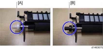
[A]: Standard roller
[B]: Imageable Area Extension Unit Type M3
![]()
During PM replacement, do not install the wrong type of roller.
4. Turn the power on.
5. Using SRA3 paper, check that a full-bleed halftone image is output, and that the image extends to 315 mm in width.