HOME PAGE | < Previous | Contents | Next >
2.18 PUNCH UNIT PU3050
Installation
Installation
Installation
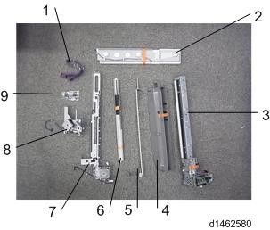
2.18.1 ACCESSORY CHECK
Description | Q’ty |
Harness | 1 |
Hopper guide plate | 1 |
Punch unit | 1 |
Hopper | 1 |
Stay | 1 |
Guide plate | 1 |
Registration Sensor unit | 1 |
Stepping motor bracket | 1 |
Tapping screws - M3 × 6 | 15 |
2.18.2 INSTALLATION PROCEDURE
![]()
When installing this option, turn the power source of the machine off, and unplug the power plug from the wall socket.
If it is installed when the power is on, it will result in an electric shock or a malfunction.
Punch Unit PU3050
1. Take out of the box, and remove the orange tape and shipping retainers.
2. Pull out the finisher interface cable, and move it away from the machine.
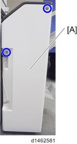
3. Finisher rear cover [A] ![]() ×2).
×2).
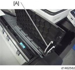
4. Remove the arm [A] of the guide plate from the finisher top cover ![]() ×1).
×1).
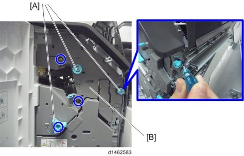
5. Open the finisher front cover, remove the three knobs [A], and remove the finisher inner cover [B] ![]() ×3,
×3, ![]() ×1).
×1).
![]()
Knobs with a lock mechanism are removed using a knob screwdriver or similar while releasing the lock.
Punch Unit PU3050
Installation
Installation
Installation
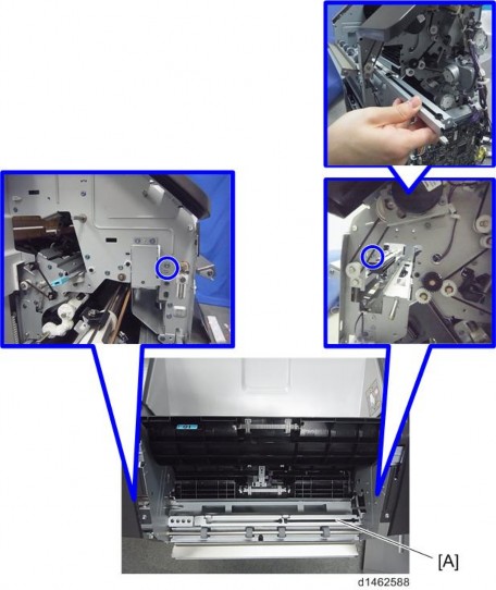
6. Cut off part of the finisher inner cover [A].
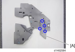
7. Guide plate [A] ![]() ×4).
×4).
Punch Unit PU3050
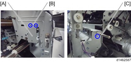
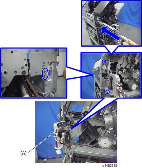
8. Insert and attach the hopper guide plate [A] from the front ![]() ×4). At this time, pass the harness [B] through the clamp [C].
×4). At this time, pass the harness [B] through the clamp [C].
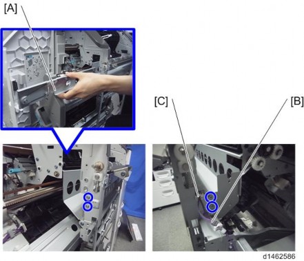
9. Attach the stay [A] ![]() ×3).
×3).
Front [B]: Insert the holes in the stay over the embossed parts on the finisher. Rear [C]: Place the axis of the stay on the notch in the finisher.
Punch Unit PU3050
Installation
Installation
Installation
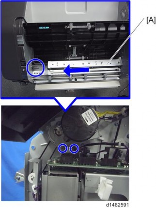
10. Insert and attach the guide plate [A] from the rear ![]() ×2).
×2).
11. Insert and attach the registration sensor unit [A] from the rear ![]() ×2).
×2).
Front: The two shafts of the unit are passed through bearings in the finisher.
Punch Unit PU3050
12. Connect the harness [A] of the hopper guide plate to the relay connector [B] of the registration sensor unit.
13. Insert and attach the punch unit [A] from the rear ![]() ×2).
×2).
Installation
Installation
Installation
Punch Unit PU3050
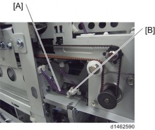
14. Attach the stepping motor bracket [A] so that the gear [B] meshes firmly ![]() ×2).
×2).
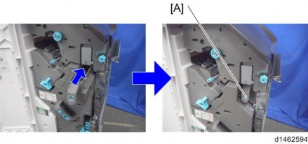
15. Insert the hopper [A].
Punch Unit PU3050
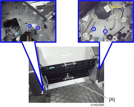
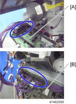
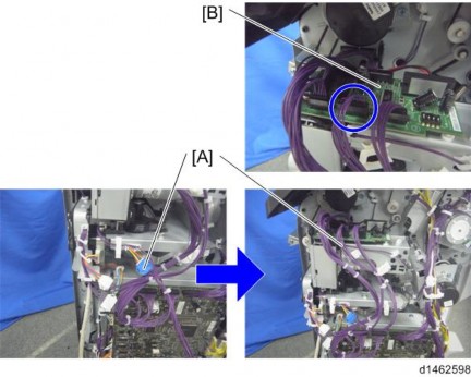
16. Connect the harness provided to the punch unit board [A] and the control board [B] of the finisher ![]() ×6).
×6).
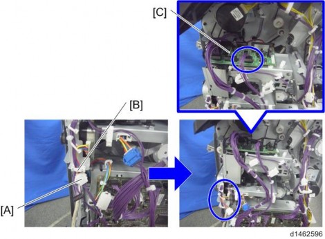
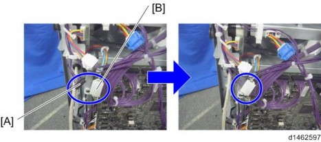
17. Remove the harness [A] from the clamp [B], and connect it to the punch unit board [C] ![]() ×1).
×1).
Punch Unit PU3050
Installation
Installation
Installation
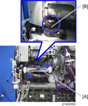
18. Connect the harness [A] of the registration sensor unit to the relay connector [B] of the harness ![]() ×1).
×1).
19. Connect the harness [A] of the stepping motor bracket to the punch unit board [B] ![]() ×1).
×1).
Punch Unit PU3050
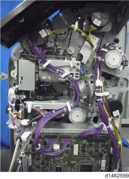
20. Clamp the harnesses.
21. Attach the finisher rear cover.
22. Attach the finisher inner cover and three knobs.
23. Close the front cover.
24. Close the top cover.
25. Attach the finisher to the machine, and connect the interface cable.
26. Turn the power switch on.
27. Check that the punch can be selected at the operation panel, and check the operation.