HOME PAGE | < Previous | Contents | Next >
Installation
Installation
Installation
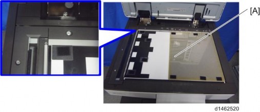
9. Close the SPDF slowly, and attach the platen sheet and SPDF.
Attaching the Sub IPU / Replacing the BCU
1. Controller cover [A] ![]() ×4)
×4)
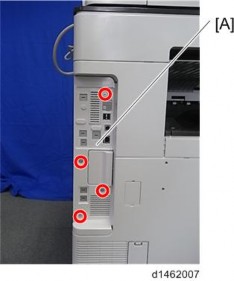
1. Rear cover [A] ![]() ×4)
×4)
SPDF DF3080
2.
3.
4.
SPDF DF3080
5. Attach the 2 clamps to the bracket provided.
Installation
Installation
Installation
6.
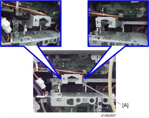
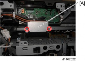
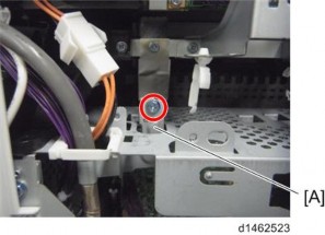
7. Retaining bracket [A] ![]() ×1)
×1)
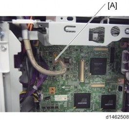
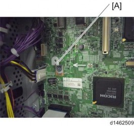
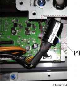
8. Pull out the connector [A] of the scanner cable.
SPDF DF3080
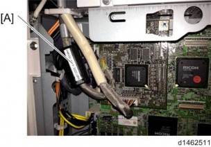
9. Attach the provided ferrite core [A] to the scanner cable.
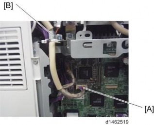
10. Attach the provided bracket [A] to the IPU board ![]() ×1)
×1)
11. Attach the IPU sub board [A], and insert the connector of the scanner cable ![]() ×3)
×3)
SPDF DF3080
Installation
Installation
Installation
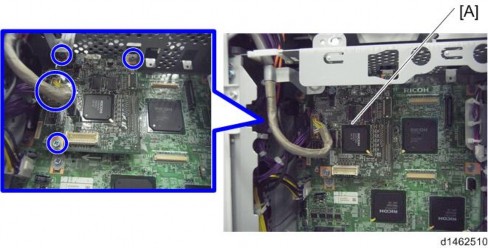
12. Replace the BCU board [A] ![]() ×2,
×2, ![]() ×4)
×4)
![]()
Since a tab is attached to the FFC, when removing, do not use force.
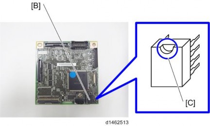
Remove the EEPROM [B] from the original BCU board with a knob screwdriver or tweezers, and replace with the BCU board in the accessories.
![]()
Remove it with the knob screwdriver or tweezers so as not to bend the terminals of the EEPROM.
![]()
Attach the EEPROM with the correct orientation so that the depression [C] is up.
SPDF DF3080
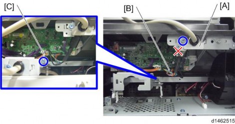
13. Attach the bracket [A] of the CIS image cable to the frame, insert the connector [B] in the SIO, and attach an earth wire [C] ![]() ×2)
×2)
14. Attach the bracket [A] of the I/F cable to the bracket attached in Step 16 ![]() ×1)
×1)
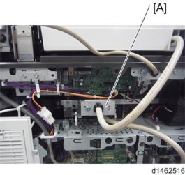
15. Attach the ferrite core [A] provided to the I/F cable.
SPDF DF3080
Installation
Installation
Installation
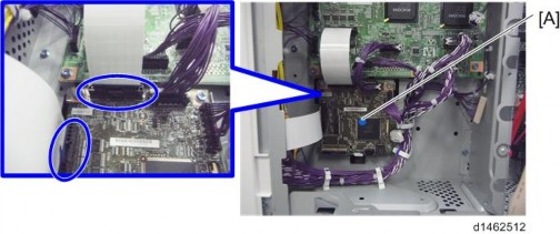
16. Insert the connector [A] of the I/F cable in the IPU small board, and fix the bracket [B] to the controller box.
17. Attach the bracket that was removed in step 17.
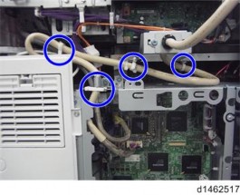
18. Attach the cable via four clamps.
19. Attach the scanner rear small cover, the scanner rear cover, the rear cover, and the controller cover.
20. Attach the decals: “Original” [A] and “Original table set” [B].