HOME PAGE | < Previous | Contents | Next >
2.11.2 INSTALLATION PROCEDURE
When installing this option, turn OFF the main power and unplug the power cord from the wall socket. If installing without turning OFF the main power, an electric shock or a malfunction may occur.
When attaching this 1-bin tray unit at the same time as Bridge Unit BU3070 or Side Tray Type M3, attach this tray first. Otherwise, the 1-bin tray’s exit tray cannot be attached due to the Bridge Unit BU3070 or Side Tray Type M3.
To use together with the “Internal Finisher SR3130”, first attach the bottom plate of Internal Finisher SR3130, and then install the 1-bin tray.
1. Remove the orange tape and shipping retainers.
2. Remove the accessories (fixing screws, etc.) provided with the machine.
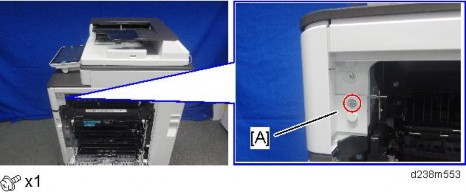
3. Open the right door, and then remove the small cover [A].
4. Remove the screw and connector, and then remove the front upper cover [A].
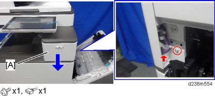
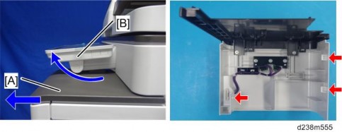
Remember that there are three tabs at the positions of the red arrows.
Tilt the operation panel [B] upward to a horizontal position, and then remove the front upper cover [A].
Installation
Installation
Installation
1 Bin Tray BN3110 (D3CQ)
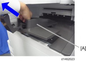
5. Remove the paper exit tray [A].
6. Remove the paper exit feeler [A].
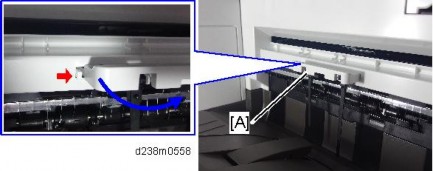
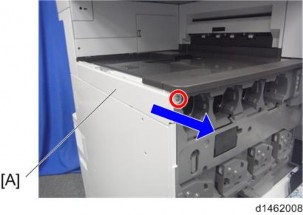
7. Open the front cover, and then remove the upper left cover [A] by pulling it towards the front ![]() ×1).
×1).
1 Bin Tray BN3110 (D3CQ)
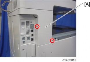
8. Remove the left rear cover [A] ![]() ×2).
×2).
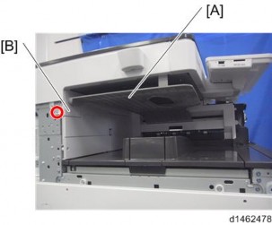
9. Remove the inverter tray [A], and tray support rod cover [B] ![]() ×1).
×1).
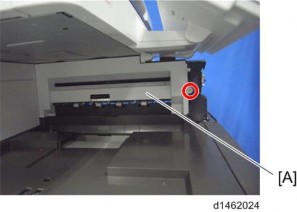
10. Remove the paper exit cover [A] ![]() ×1).
×1).
1 Bin Tray BN3110 (D3CQ)
Installation
Installation
Installation
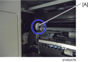
11. Attach the gear [A] provided with the accessories.
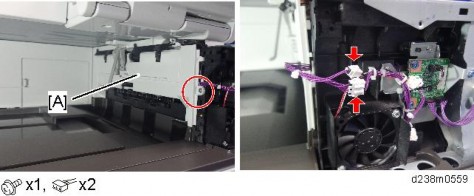
12. Attach the 1-bin tray unit [A].
Make sure to engage it with the gear attached in the previous step.
Take care that the harness is not trapped between the 1-bin tray unit and the machine frame.
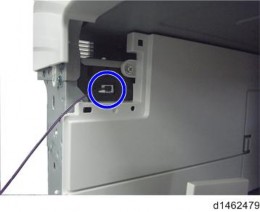
13. Attach the harness provided with the accessories.
1 Bin Tray BN3110 (D3CQ)
14. Attach the tray support bar [A] ![]() ×1).
×1).
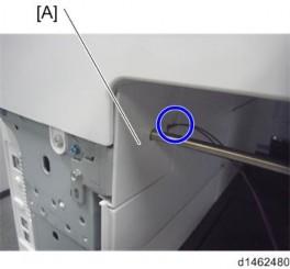
When attaching the tray support bar [A], make sure that the harness attached in the previous step goes through the slit in the tray support bar circled in blue and comes outside of it as shown below.
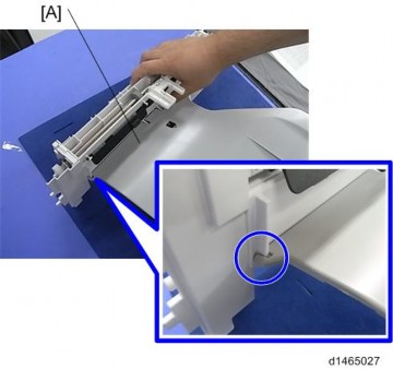
15. Hook the 1-bin tray [A] onto the 1-bin tray unit, aligning the positions in the blue circle.
1 Bin Tray BN3110 (D3CQ)
Installation
Installation
Installation
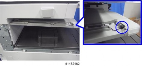
16. Connect the harness to the 1-bin tray, and bring it around.
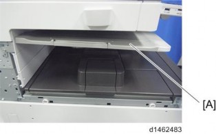
17. Insert the tray support bar firmly in the 1-bin tray, and attach the harness cover [A].
18. Reattach the left rear cover, upper left cover and front upper cover, and close the right door.
19. Reattach the paper exit tray and paper exit feeler.
20. Turn ON the main power.
21. Check that output to this tray can be selected on the operation panel, and check operation.