HOME PAGE | < Previous | Contents | Next >
Exterior Cover/ Air Flows (Fan Control)
7.14.2 MECHANISM
By installing the duct corresponding to each fan, the air flow is efficiently controlled to a cooling target. Moreover, improvement in quietness and energy-saving efficiency is achieved by performing stepwise operation of the fan according to the imaging temperature.
Cooling of PSU
Air taken in by the PSU cooling fan is guided near the cooling target by the duct, and is efficiently cooled.
Cooling of Toner Supply Parts
Air taken in with the toner supply cooling fan is guided to circulate around the toner bottle, and is discharged from the side of the delivery tray to outside the machine. It is aimed to achieve heat insulation from the stack of paper to the toner bottle by reducing the melting point of the toner.
Cooling of PCDU parts
By discharging air taken in from the development intake fan at the front, from the ozone exhaust fan at the rear, a uniform air flow is attained and efficient cooling is realized. Discharge of ozone and scattering of toner are prevented by installing an ozone filter and a dust filter in front of the ozone exhaust fan.
Cooling of Fusing Parts
Air taken in from the paper discharge cooling fan at the front is discharged from the fusing heat discharge fan at the rear to outside the machine. By cooling the paper immediately after fusing, not only cooling of the fusing exit sensor but also reduction of stored heat of the stacked paper and reduction of curl are realized. This also serves to prevent condensation on the paper discharge guide sheet. As a measure against odor, a deodorization filter is installed downstream from the fusing exhaust fan.
Cooling in Controller Box
Air is circulated by the controller box cooling fan installed in the controller box, preventing temperature rise in the controller box.
Crisis Management When Temperature Rises in the Machine
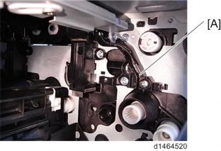
In order to suppress excessive temperature rise in the machine and maintain equipment quality, a temperature sensor (imaging temperature sensor (thermistor)) [A] is installed in the machine. The imaging temperature sensor (thermistor) detects the temperature environment in the machine, and controls cooling operation.
Detailed Descriptions
Detailed Descriptions
Detailed Descriptions
Exterior Cover/ Air Flows (Fan Control)

Overview of cooling operation in the machine
The temperature in the machine is detected during output and after output, and the interior of the machine is cooled by fan operation (stepwise operation of fan, prolonged fan rotation after paper has passed through) according to the temperature inside the machine.
However, if the temperature inside the machine rises significantly due to passing a large volume of paper, in addition to fan operation, the CPM is specified to control the temperature in the machine.
Cooling operation during output
Perform cooling operation under the following conditions.
Imaging temperature | Less than 34 | 34 | 35 | 36 | 37 | 38 | 40*1 |
Fusing exhaust fan | ON | ON | ON | ON | ON | ON | ON |
Ozone exhaust fan | 20% | 20% | 30% | 30% | 40% | 40% | 40% |
Toner supply cooling fan | - | - | - | ON | ON | ON | ON |
Development intake fan *3 | - | - | - | ON | ON | ON | ON |
PSU cooling fan*2 | ON | ON | ON | ON | ON | ON | ON |
The operation start temperature can be modified by SP.
*1 If the imaging temperature reaches 41°C each fan will continue operating until it falls by 2°C.
*2 Operating condition:
When the time interval from the previous job is less than 10 minutes. Or, when the time interval from the previous job is more than 10 minutes, and 5 minutes have elapsed from start of machine.
*3 Operating condition:
For 36°C or above, full speed rotation at 24V