HOME PAGE | < Previous | Contents | Next >
Correction Operation Outline
1. The machine corrects the ID sensor output by Vsg adjustment
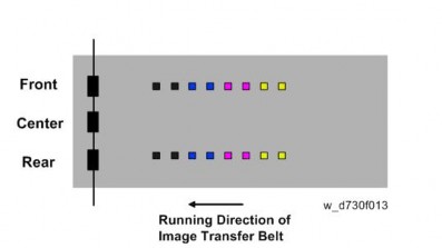
2. The machine creates the MUSIC pattern on the transfer belt with toner of each color.
3. The machine reads the MUSIC pattern on the transfer belt and detects the positions of the line patterns.
4. The machine calculates the amount of color registration or skew from the detected positions.
5. The machine determines the correction for the color registration, by calculating the required main scan magnification shift, main scan magnification deviation, main scan registration shift, skew correction value, and sub scan registration shift from the detected positions.
7.6.4 REAL TIME PROCESS CONTROL
During printing, 5 mm patterns are created outside the normal imaging area on the transfer belt, and the image density is corrected in the real time, to improve printing of solid areas. However, note that if the optional Imageable Area Extension Unit is installed, this process is disabled.

Normally, the real time control is done once every 10 sheets, but it could be done once every 5 sheets depending on the density detection level.
The frequency depends on the following SPs.
SP3-301-001: RTP Pattern:Set:Create Intrvl:BW
SP3-301-002: RTP Pattern:Set:Create Intrvl:FC
To see the latest result, check the following SPs. If there is an error, the result will not be updated.
SP3-300-001 to 004 RTP Pattern:Disp:M/A(Latest):Each Color
SP3-300-001 to 004 RTP Pattern:Disp:M/A(Target):Each Color