HOME PAGE | < Previous | Contents | Next >
4.5.2 USB CABLE
1. Rear cover (page 4-14)
2. Scanner right cover (page 4-34)
3. Controller box cover (page 4-182)
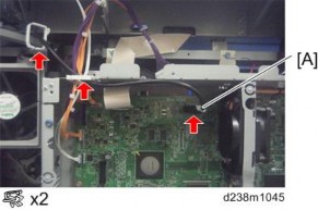
4. Disconnect the USB cable [A]
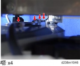
5. Remove the clamps on the cables under the scanner unit.
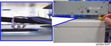
When removing a clamp, insert a long flathead screwdriver or such a tool from the side to remove it.
Replacement and Adjustment
Replacement and Adjustment
Replacement and Adjustment
Smart Operation Panel
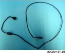
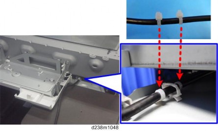
The cable has a set of 2 cable ties. When attaching the cable, position the clamp between the two cable ties.
