HOME PAGE | < Previous | Contents | Next >
Card Reader Bracket Type 3352 (D593-61)
2.34 CARD READER BRACKET TYPE 3352 (D593-61)
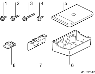
2.34.1 ACCESSORY CHECK
Check the quantity and condition of the accessories against the following list.
No. | Description | Q'ty | For This Model |
1 | Screw: M3 x 8 | 2 | Yes |
2 | Screw: M3 x 14 | 1 | Not used |
3 | Screw: M4 x 25 | 1 | Yes |
4 | Tapping Screw: M3 x 10 | 3 | Yes |
5 | Upper Tray | 1 | Yes |
6 | Lower Tray | 1 | Yes |
7 | Tray Bracket | 1 | Yes |
8 | Clamp | 5 | Yes |
2.34.2 INSTALLATION PROCEDURE
When installing this option, turn OFF the main power and unplug the power cord from the wall socket. If installing without turning OFF the main power, an electric shock or a malfunction may occur.
1. Open the ADF.
Card Reader Bracket Type 3352 (D593-61)
Installation
Installation
Installation
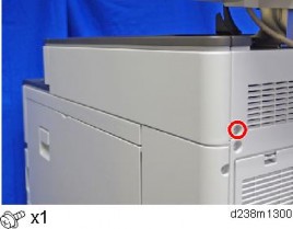
2. Remove a screw for the scanner right cover.
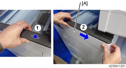
3. Remove the scanner right cover [A].
Remove the hook at the top, and then slide the cover towards the rear.
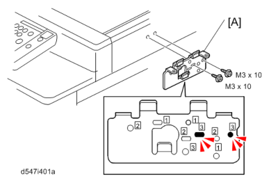
4. Make 2 screw holes in the removed scanner right cover with a screwdriver or drill.
Make the screw holes to be smaller than the screw size.
5.
6. Attach the tray bracket [A] to the scanner right cover ![]() x2: M3x10 tapping screw).
x2: M3x10 tapping screw).
For this model, use the screw holes marked "3" on the table bracket.
Card Reader Bracket Type 3352 (D593-61)
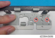
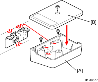
7. Attach the lower tray [A] to the tray bracket ![]() x2: M3 x 8).
x2: M3 x 8).
8. Attach the upper tray [B] to the tray bracket ![]() x1: M3 x 10).
x1: M3 x 10).
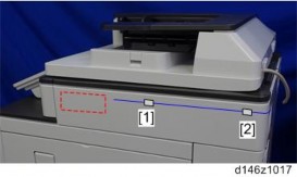
9. Attach the clamps ([1] to [5]) and route the harness around the machine as shown.
The USB cable is not supplied. Use a commercially available USB cable.
Scanner Right Cover
Card Reader Bracket Type 3352 (D593-61)
Installation
Installation
Installation
Rear Cover
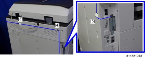
10. Connect the USB cable to the USB A slot.