HOME PAGE | < Previous | Contents | Next >
1. Operation panel unit (page 1)
2. Bottom cover [A] ![]() ×4)
×4)
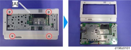
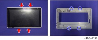
There are four hooks inside the operation panel unit. Before removing the operation panel bottom cover, check the photos below.
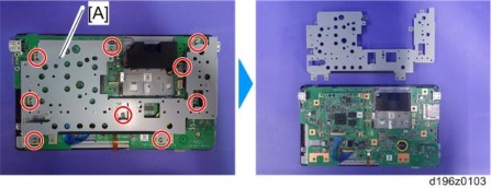
3. Base bracket [A] ![]() ×9)
×9)
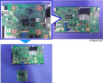
4. Remove the fixing screws ![]() ×4) on the CPU board [A], and remove the CPU board from the micro computer board.
×4) on the CPU board [A], and remove the CPU board from the micro computer board.
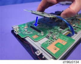
Make sure that the orientation of the connector is correct when attaching the CPU board.
5. Lift the fastener of the LCD I/F cable on the CPU board side.
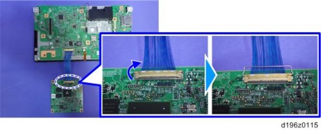
6. CPU board [A] (LCD I/F cable ×1)
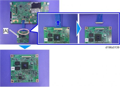
After replacing the CPU board, make sure that the latest version of the firmware is installed on the Smart Operation Panel. Update it if necessary. (page 62 "Updating the Smart Operation Panel")