HOME PAGE | < Previous | Contents | Next >
INTERNAL FINISHER SR3130 (D690)
INTERNAL FINISHER SR3130 (D690)
INTERNAL FINISHER SR3130 (D690)
1. REPLACEMENT AND ADJUSTMENT
1.1 MAIN UNIT
1.1.1 INTERNAL FINISHER
1. Disconnect the interface cable connected to the main machine.
2. Open the front cover [A]
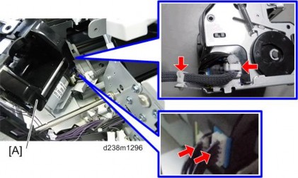
3.
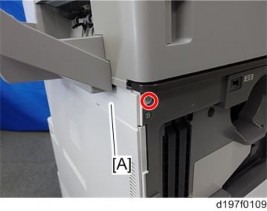
4. Left rear cover [A] ![]() ×2, hook×1)
×2, hook×1)
Main Unit
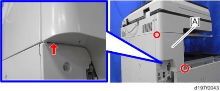
5. Internal finisher [A] ![]() ×1)
×1)
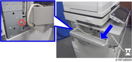
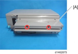
6. Bridge guide plate [A] ![]() ×2)
×2)
Exterior Covers and Trays
INTERNAL FINISHER SR3130 (D690)
INTERNAL FINISHER SR3130 (D690)
INTERNAL FINISHER SR3130 (D690)
1.2 EXTERIOR COVERS AND TRAYS
1.2.1 FINISHER FRONT COVER
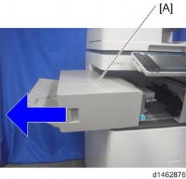
1. Pull the finisher [A]
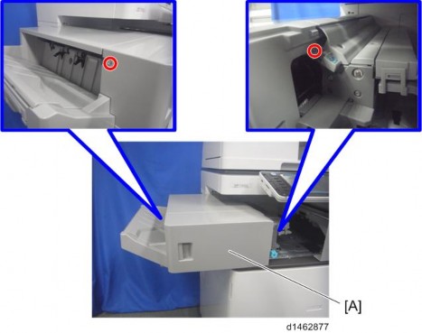
2. Finisher front cover [A] ![]() ×2)
×2)
Exterior Covers and Trays
1.2.2 FINISHER UPPER COVER
1. Finisher front cover (page 3)
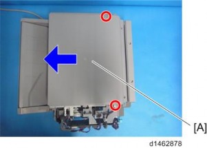
2. Finisher upper cover [A] ![]() ×2)
×2)
1.2.3 FINISHER REAR COVER
1. Internal finisher (page 1)
2. Finisher rear cover [A] ![]() ×2)
×2)
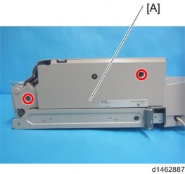
Exterior Covers and Trays
INTERNAL FINISHER SR3130 (D690)
INTERNAL FINISHER SR3130 (D690)
INTERNAL FINISHER SR3130 (D690)
1.2.4 PAPER EXIT TRAY
1. Left lower cover [A] ![]() ×2)
×2)
2.
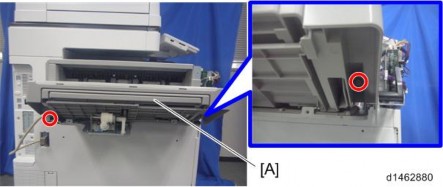
Exterior Covers and Trays
1.2.5 PAPER EXIT COVER
1. Paper exit tray (page 5)
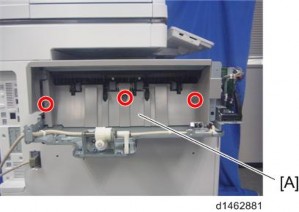
2. Paper exit cover [A] ![]() ×3,
×3, ![]() ×3,
×3, ![]() ×2).
×2).
Board
INTERNAL FINISHER SR3130 (D690)
INTERNAL FINISHER SR3130 (D690)
INTERNAL FINISHER SR3130 (D690)
1.3 BOARD
1.3.1 CONTROLLER BOARD
When a controller board is replaced, use the same DIP switch settings as those of the controller board before replacement.
1. Finisher front cover (page 3)
2. Controller board [A] ![]() ×3,
×3, ![]() ×all, plastic rivet×1)
×all, plastic rivet×1)
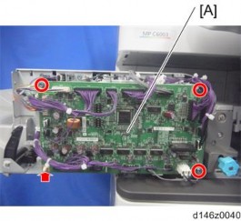
3. Release four clamps and remove the harness bracket [A] on the controller board bracket. ![]() ×4)
×4)
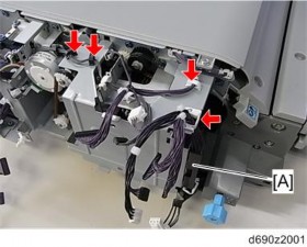
Board
4. Controller board bracket [A] ![]() x2)
x2)
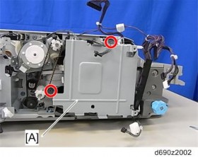
Sensors
INTERNAL FINISHER SR3130 (D690)
INTERNAL FINISHER SR3130 (D690)
INTERNAL FINISHER SR3130 (D690)
1.4 SENSORS
1.4.1 ENTRANCE SENSOR
1. Internal finisher (page 1)
2. Open/Close upper cover [A] ![]() ×2)
×2)
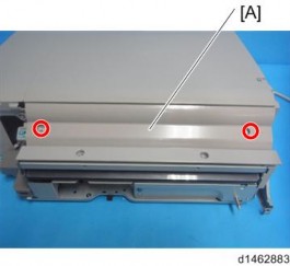
3. Entrance sensor unit [A] ![]() ×1,
×1, ![]() ×1,
×1, ![]() ×1)
×1)
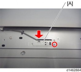
Sensors
4. Entrance sensor [A]
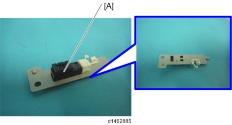
1.4.2 PAPER EXIT FULL SENSOR
1. Paper exit tray (page 5)
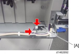
2. Paper exit full sensor [A] ![]() ×1,
×1, ![]() ×1)
×1)
Sensors
INTERNAL FINISHER SR3130 (D690)
INTERNAL FINISHER SR3130 (D690)
INTERNAL FINISHER SR3130 (D690)
1.4.3 STACK HEIGHT LEVER HP SENSOR
1. Paper exit cover (page 6)
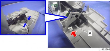
2. Stack Height Lever HP Sensor [A] ![]() ×1)
×1)
1.4.4 PAPER SURFACE SENSOR
1. Paper exit cover (page 6)
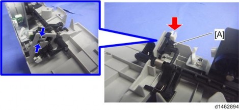
2. Paper surface sensor [A] ![]() ×1)
×1)
Sensors
1.4.5 TRANSPORT SENSOR
1. Finisher upper cover (page 4)
2. Transport sensor unit [A] ![]() ×1,
×1, ![]() ×1,
×1, ![]() ×1)
×1)
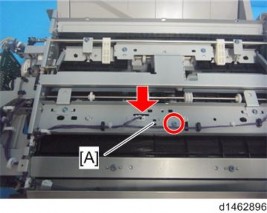
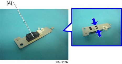
3. Transport sensor [A]
Sensors
INTERNAL FINISHER SR3130 (D690)
INTERNAL FINISHER SR3130 (D690)
INTERNAL FINISHER SR3130 (D690)
1.4.6 POSITIONING ROLLER HOME POSITION SENSOR
1. Finisher upper cover (page 4)
2. Finisher rear cover (page 4)
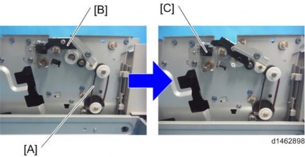
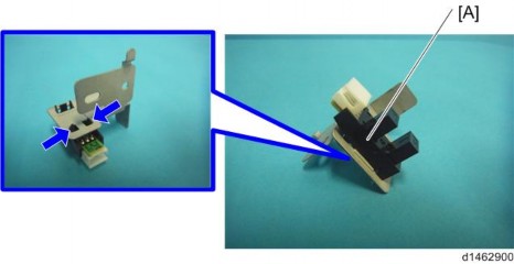
3. Rotate the timing belt [A], and release the positioning roller arm unit [B] from the positioning roller HP sensor [C].
4. Positioning roller home position sensor unit [A] ![]() ×1,
×1, ![]() ×1,
×1, ![]() ×1)
×1)
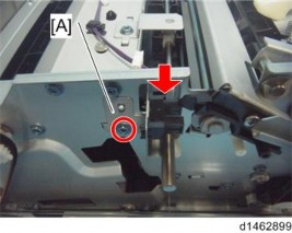
5. Positioning roller home position sensor [A]
Sensors
1.4.7 PAPER EXIT GUIDE PLATE HOME POSITION SENSOR
1. Controller board (page 7)
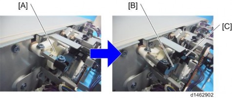
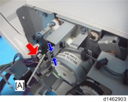
2. Rotate the paper exit guide plate gear [A] counterclockwise, and release the paper exit guide plate [B] from the paper exit guide plate HP sensor [C].
3. Paper Exit Guide Plate Home Position Sensor [A] ![]() ×1)
×1)
Sensors
INTERNAL FINISHER SR3130 (D690)
INTERNAL FINISHER SR3130 (D690)
INTERNAL FINISHER SR3130 (D690)
1.4.8 SHIFT ROLLER HOME POSITION SENSOR
1. Controller board bracket (page 7)
2. Shift roller home position sensor unit [A] ![]() ×1,
×1, ![]() ×1,
×1, ![]() ×2)
×2)
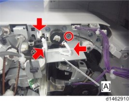
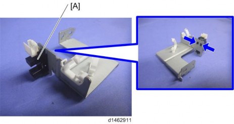
3. Shift roller home position sensor [A]
Sensors
1.4.9 STAPLER HOME POSITION SENSOR
1. Controller board bracket (page 7)
2. Knob [A]
3.
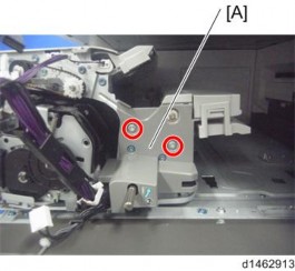
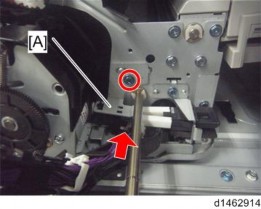
4. Stapler home position sensor unit [A] ![]() ×1,
×1, ![]() ×1)
×1)
Sensors
INTERNAL FINISHER SR3130 (D690)
INTERNAL FINISHER SR3130 (D690)
INTERNAL FINISHER SR3130 (D690)
5. Stapler home position sensor [A]
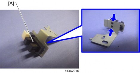
If it is difficult to remove or attach the sensor, push the stapler unit inside.
Sensors
1.4.10 JOGGER FENCE HOME POSITION SENSOR (FRONT)
1. Paper exit cover (page 6)
2. Jogger fence home position sensor (front) unit [A] ![]() ×1,
×1, ![]() ×1,
×1, ![]() ×1)
×1)
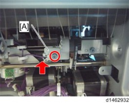
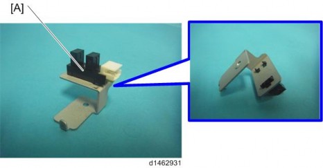
3. Jogger fence home position sensor (front) [A]
Sensors
INTERNAL FINISHER SR3130 (D690)
INTERNAL FINISHER SR3130 (D690)
INTERNAL FINISHER SR3130 (D690)
1.4.11 JOGGER FENCE HOME POSITION SENSOR (REAR)
1. Paper exit cover (page 6)
2. Jogger fence home position sensor (rear) unit [A] ![]() ×1,
×1, ![]() ×1)
×1)
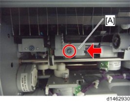
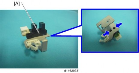
3. Jogger fence home position sensor (rear) [A]
Sensors
1.4.12 STAPLER TRAY JAM SENSOR
1. Paper exit cover (page 6)
2. Paper exit roller unit [A] ![]() ×1)
×1)
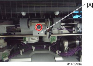
3. Stapler tray jam sensor unit [A] ![]() ×1,
×1, ![]() ×1,
×1, ![]() ×1)
×1)
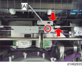
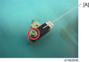
4. Stapler tray jam sensor [A] ![]() ×1)
×1)
Sensors
INTERNAL FINISHER SR3130 (D690)
INTERNAL FINISHER SR3130 (D690)
INTERNAL FINISHER SR3130 (D690)
1.4.13 PAPER SENSOR
1. Jogger fence motor (rear) (page 30)
2. Jogger fence motor (rear) bracket [A] ![]() ×2,
×2, ![]() ×3)
×3)
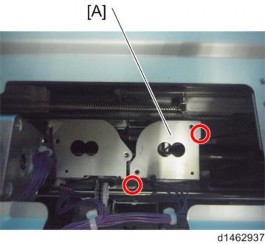
3. Paper sensor unit [A] ![]() ×1,
×1, ![]() ×1,
×1,![]() ×1)
×1)
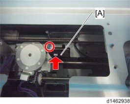
4. Paper sensor [A]
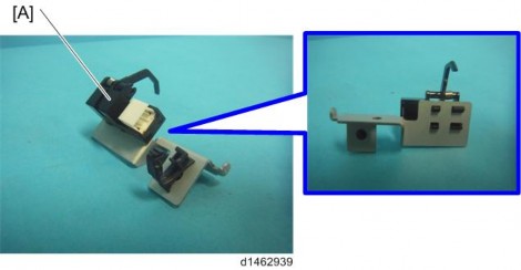
When installing this sensor, be careful not to damage the sensor actuator.
Motors
1.5 MOTORS
1.5.1 ENTRANCE MOTOR
1. Finisher rear cover (page 4)
2. Finisher right rear bracket [A] ![]() ×2)
×2)
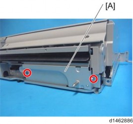
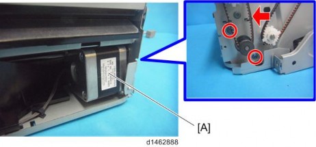
3. Entrance motor [A] ![]() ×2,
×2, ![]() ×1, Timing belt×1)
×1, Timing belt×1)
Motors
INTERNAL FINISHER SR3130 (D690)
INTERNAL FINISHER SR3130 (D690)
INTERNAL FINISHER SR3130 (D690)
1.5.2 TRAY LIFT MOTOR
1. Paper exit tray (page 5)
2. Tray lift motor unit [A] ![]() ×2,
×2, ![]() ×1,
×1, ![]() ×1)
×1)
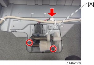
3. Cam [A], bearing [B] ![]() ×1)
×1)
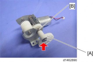
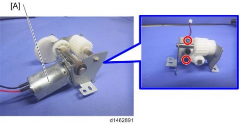
4. Tray lift motor [A] ![]() ×2)
×2)
Motors
1.5.3 STACK HEIGHT LEVER MOTOR
1. Paper exit cover (page 6)
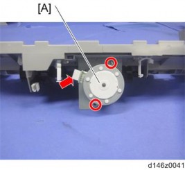
2. Stack height lever motor [A] ![]() ×2,
×2, ![]() ×1)
×1)
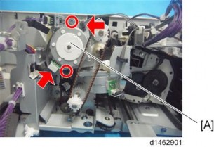
1.5.4 PAPER EXIT GUIDE PLATE MOTOR
1. Controller board (page 7)
2. Paper exit guide plate motor [A] ![]() ×2,
×2, ![]() ×1,
×1, ![]() ×1)
×1)
Motors
INTERNAL FINISHER SR3130 (D690)
INTERNAL FINISHER SR3130 (D690)
INTERNAL FINISHER SR3130 (D690)
1.5.5 POSITIONING ROLLER MOTOR
1. Paper exit cover (page 6)
2. Finisher rear cover (page 4)
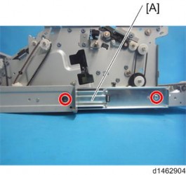
3. Rear rail [A] ![]() ×2)
×2)
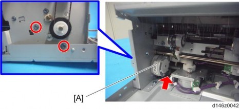
4. Positioning roller motor [A] ![]() ×2,
×2, ![]() ×1)
×1)
Motors
1.5.6 SHIFT MOTOR
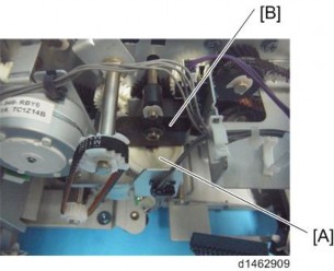
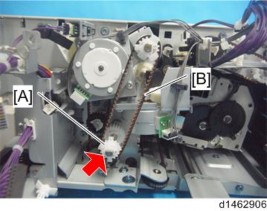
After attaching, rotate the knob, and check that all gear trains can rotate.
After attachment, when the cam [A] is rotated, check that the link [B] interlocks.
1. Controller board bracket (page 7)
2. Pulley [A], Timing belt [B] ![]() ×1)
×1)
3. Shift motor unit [A] ![]() ×2,
×2, ![]() ×1,
×1, ![]() ×1)
×1)
INTERNAL FINISHER SR3130 (D690)
INTERNAL FINISHER SR3130 (D690)
INTERNAL FINISHER SR3130 (D690)
Motors
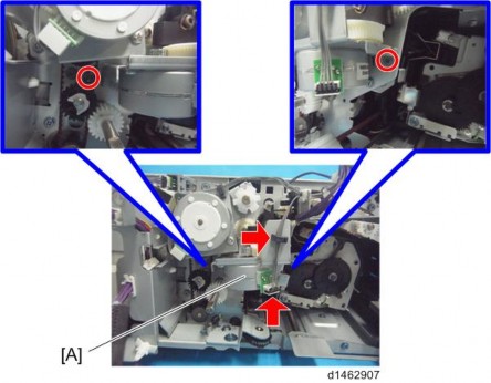
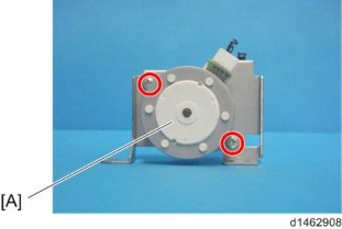
4. Shift motor [A] ![]() ×2).
×2).
Motors
1.5.7 STAPLER RETREAT MOTOR
When placing the finisher upside down, be careful not to deform the frame.
1. Paper exit cover (page 6)
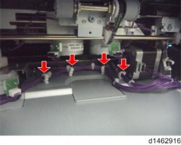
2. Release the four clamps ![]() ×4).
×4).
3. Place the internal finisher upside down on the table while holding the parts shown below [A].
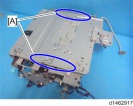
Hold the parts [A] shown below to lift the internal finisher. Otherwise, other brackets and parts may be deformed.
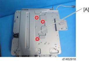
4. Base cover [A] ![]() ×3)
×3)
Motors
INTERNAL FINISHER SR3130 (D690)
INTERNAL FINISHER SR3130 (D690)
INTERNAL FINISHER SR3130 (D690)
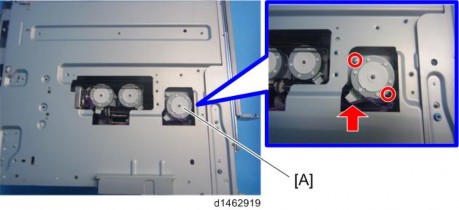
5. Stapler retreat motor ![]() ×2,
×2, ![]() ×1)
×1)
Motors
1.5.8 JOGGER FENCE MOTOR (FRONT / REAR)
1. Base cover (page 28)
2. Jogger fence motor (front) [A] ![]() ×2,
×2, ![]() ×1, Timing belt×1)
×1, Timing belt×1)
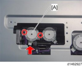
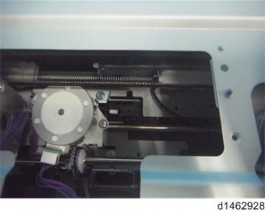
During re-assembly, remove the jogger fence motor (rear) bracket, and check that the motor pulley has not separated from the timing belt.
3. Jogger fence motor (rear) [A] ![]() ×2,
×2, ![]() ×1, Timing belt×1)
×1, Timing belt×1)
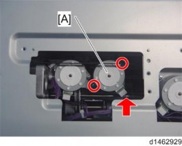
During re-assembly, check that the motor pulley has not separated from the timing belt.
Motors
INTERNAL FINISHER SR3130 (D690)
INTERNAL FINISHER SR3130 (D690)
INTERNAL FINISHER SR3130 (D690)
1.5.9 TRANSPORT MOTOR
1. Paper exit cover (page 6)
2. Controller board (page 7)
3. Finisher rear cover (page 4)
4. Pulley [A], Timing belt [B] ![]() ×1).
×1).
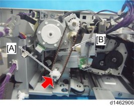
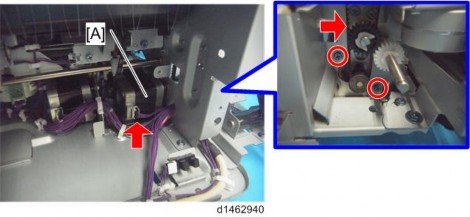
5. Transport Motor [A] ![]() ×2,
×2, ![]() ×1, Timing belt×1)
×1, Timing belt×1)
Motors
1.5.10 PAPER EXIT MOTOR
1. Transport motor (page 31)
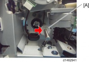
2. Controller board bracket (page 7) 3. Gear [A] ![]() ×1)
×1)
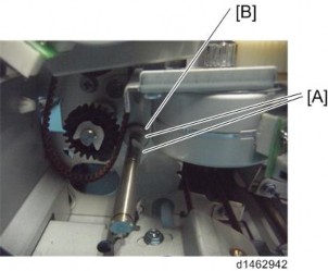
4. Two clip rings [A] and Shaft bracket [B] ![]() ×2).
×2).
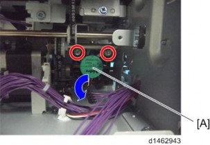
5. Remove the screws of the fan [A] and then lay it down ![]() ×2).
×2).
Motors
INTERNAL FINISHER SR3130 (D690)
INTERNAL FINISHER SR3130 (D690)
INTERNAL FINISHER SR3130 (D690)
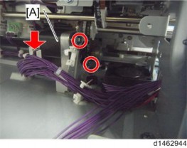
6. Paper Exit Motor [A] ![]() ×2,
×2, ![]() ×1).
×1).
Stapler Unit
1.6 STAPLER UNIT
1. Controller board bracket (page 7)
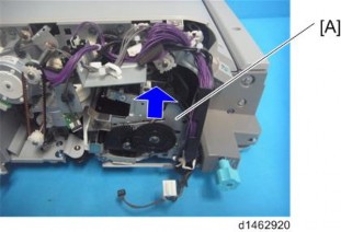
2. Insert the stapler unit [A] into the rear.
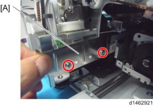
3. Rear trailing edge fence [A] ![]() ×2)
×2)
4. Stapler home position sensor (page 16)
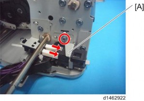
5. Cover open/close switch unit [A] ![]() ×1,
×1, ![]() ×2)
×2)
Stapler Unit
INTERNAL FINISHER SR3130 (D690)
INTERNAL FINISHER SR3130 (D690)
INTERNAL FINISHER SR3130 (D690)
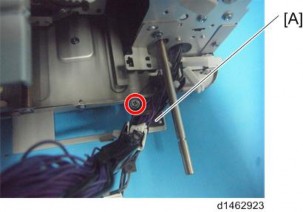
6. Harness guide unit [A] ![]() ×1)
×1)
7. Move the stapler unit to the front, and remove the cartridge [A].
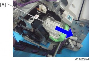
During re-assembly, install the cartridge last.
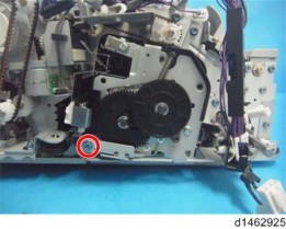
8. Remove the unit fixing screw of the stapler unit. ![]() ×1)
×1)
Stapler Unit
9. Stapler unit [A] ![]() ×2,
×2, ![]() ×2)
×2)
