HOME PAGE | < Previous | Contents | Next >
Punch Unit Installation (D570)
2.11.2 INSTALLATION PROCEDURE
![]()
Installation
Installation
Installation
Unplug the main machine power cord before starting the following procedure. If the 2000/3000-sheet booklet finisher has been installed, disconnect it and pull it away from the machine.
1. Remove all tapes and shipping retainers.
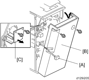
2. If the finisher is connected to the copier, disconnect the power connector [A] and separate the finisher from the copier.
3. Remove the rear cover [B] ![]() x 2) and open the front door.
x 2) and open the front door.
![]()
At the base of the back cover, be sure to disconnect the tabs that fasten the cover to the frame.
4. Remove the guide plate [C] ![]() x 2).
x 2).
Punch Unit Installation (D570)
5. Remove the shipping retainer [A] ( x 2) from the punch unit.
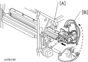
6. Move the punch unit [A] along its rails into the finisher. Make sure that the pin engages correctly at the front and rear.
7. Connect the cables [B] of the finisher to the connectors (CN601 and CN602) on the punch unit board ![]() x 2,
x 2, ![]() x 1).
x 1).
The cables [B] are coiled and attached to the PCB.
Punch Unit Installation (D570)
Installation
Installation
Installation
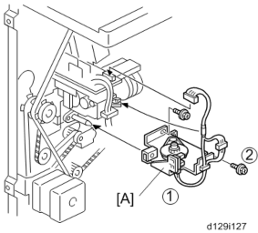
8. Attach the slide drive unit [A] to the finisher and connect it to the punch unit ![]() x 2,
x 2, ![]() x 1). Push in the slide drive unit at
x 1). Push in the slide drive unit at ![]() when you attach the screw
when you attach the screw ![]() .
.
9. Make sure that the punch unit moves freely and is not blocked by the screws.
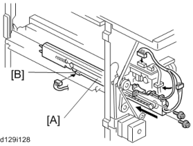
10. Put the side-to-side detection unit [A] in the machine. Make sure that the two pins are engaged correctly at the front.
11. Make sure that the side-to-side detection unit moves smoothly on its rails. If it does not, make sure that the rails are aligned with their grooves.
12. Attach the side-to-side detection unit and connect it at the rear ![]() x 2,
x 2, ![]() x 1,
x 1, ![]() x 1).
x 1).
13. Pull the short connector out of the connector [B], then connect the cable of the finisher ![]() x 1).
x 1).
Punch Unit Installation (D570)
![]()
This is the 3-pin connector.
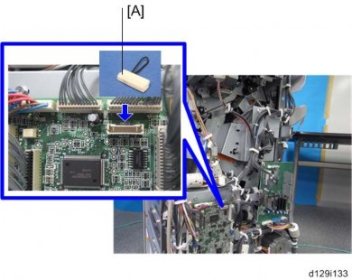
14. Connect "Wire harness: short-circuit" [A] to the CN110 connector.
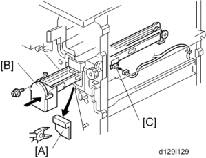
15. At the front, use a pair of wire cutters to remove the part [A] of the cover.
16. Install the punch-waste transport unit [B] in the finisher.
17. Make sure that the punch-waste transport unit moves smoothly on its rails. If it does not, make sure that the rails are aligned with the grooves.
18. Remove the short connector from the connector [C].
Punch Unit Installation (D570)
![]()
This is the 4-pin connector.
Installation
Installation
Installation
19. Connect the cable to connector [C] and attach the punch-waste transport unit ![]() x 1,
x 1, ![]() x 1,
x 1, ![]() x 1).
x 1).
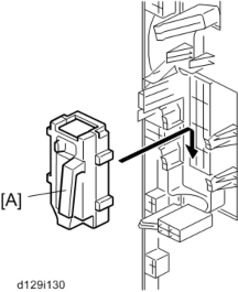
20. Set the hopper [A] in its holder.
21. Reassemble the finisher, and then install it on the main machine.
22. Connect the power cord to the outlet, and then turn the main power switch on.
23. Check the punch unit operation.