HOME PAGE | < Previous | Contents | Next >
G3 Interface Board Installation
1.2.2 INSTALLATION: ONE G3 BOARD

2. If the fax unit is already installed in the machine, remove the FCU ![]() x 4). If not, remove the FCU cover
x 4). If not, remove the FCU cover ![]() x 3).
x 3).
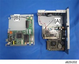
3. Attach one end (short length) of the flat cable to the connector [A] of the FCU board.
4. Attach the other end (long length) of the flat cable to the connector [B] of the CCUIF.

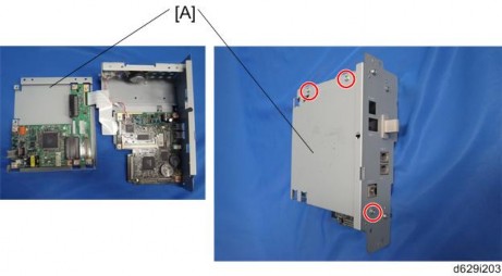
5. Attach the SG3 interface unit [A] ![]() x 3).
x 3).
Fax Option Type 5002 (D629)
Fax Option Type 5002 (D629)
Fax Option Type 5002 (D629)
G3 Interface Board Installation

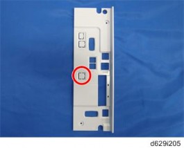
6. Remove the knockout for LINE 2 from the controller cover.
7. Install the FCU in the machine (for details, refer to Fax Option Installation).
8. Reattach the controller cover ![]() x2).
x2).
9. Connect the telephone cord to the LINE 2 jack.
10. Enter the service mode. Set bit 1 of communication switch 16 to "1" (SP1-104-023) for PSTN-2.
11. Turn the main switch off and on.
12. Print out the system parameter list. Then check that "G3" shows as an option.
13. Set up and program the items required for PSTN-2 communications.
14. Attach the FCC decal near the serial number plate of the mainframe.