HOME PAGE | < Previous | Contents | Next >
2.7 CASTER TABLE TYPE M3
Installation
Installation
Installation
2.7.1 ACCESSORY CHECK
No. | Description | Q’ty |
1 | Right Lower Cover | 1 |
2 | Securing Bracket | 2 |
3 | Screws (M4 × 10) | 2 |
4 | Screw with Spring Washer (M4 × 10) | 1 |
2.7.2 INSTALLATION PROCEDURE
![]()
Removal of stabilizers must always be with the consent of the customer. Do not remove them at your own judgment.
The machine must be held at the correct locations, and must be lifted slowly.
If it is lifted with force, handled carelessly or dropped, it will result in an injury.
If installing this option, turn the power to the machine off, and unplug the power plug from the wall socket.
If it is installed when the power is on, it will result in an electric shock or malfunction.
Be sure to join the machine and caster table to prevent equipment from falling over.
If it is not joined, the machine will move or fall over, which will result in an injury.
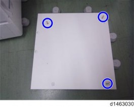
1. Attach the 3 locating pins.
Caster Table Type M3
2. Holding the grips on the machine, align with the locating pin, and place the machine on the caster table.
![]()
When you lift the machine, hold the lifting handles.
In particular, do not lift it by holding the scanner unit, etc., (as it may deform). .
Do not put the machine down on the caster table as a temporary resting place. This may cause the machine to deform. Always connect the machine and caster unit properly.
3. Pull out the 2nd paper feed tray.
4. Using a securing bracket, fix the machine to the paper tray unit (spring washer : screw: M4×10: 1).
5. Attach the securing brackets [A] at 2 positions to left and right at the rear of the machine (screws: 1 each).
6. Return the paper feed tray to the machine.