HOME PAGE | < Previous | Contents | Next >
Safety and Symbols
This manual uses several symbols and abbreviations. The meaning of those symbols and abbreviations are as follows:
| Clip ring |
| Screw |
| Connector |
| Clamp |
SEF | Short Edge Feed |
LEF | Long Edge Feed |
[A] Short Edge Feed (SEF)
[B] Long Edge Feed (LEF)
Trademarks
Microsoft®, Windows®, and MS-DOS® are registered trademarks of Microsoft Corporation in the United States and /or other countries.
PostScript® is a registered trademark of Adobe Systems, Incorporated.
PCL® is a registered trademark of Hewlett-Packard Company. Ethernet® is a registered trademark of Xerox Corporation.
PowerPC® is a registered trademark of International Business Machines Corporation.
Other product names used herein are for identification purposes only and may be trademarks of their respective companies. We disclaim any and all rights involved with those marks.
The Aim of Anti-tip Components and Precautions
The anti-tip components are necessary for meeting the requirements of IEC60950-1, the international standard for safety.
The aim of these components is to prevent the products, which are heavy in weight, from toppling as a result of people running into or leaning onto the products, which can lead to serious accidents such as persons becoming trapped under the product. (U.S.: UL60950-1, Europe: EN60950-1) Therefore, removal of such components must always be with the consent of the customer.
Do not remove them at your own judgment.
Rear Cover
LCIT RT3030 (D696)
LCIT RT3030 (D696)
LCIT RT3030 (D696)
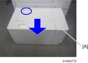
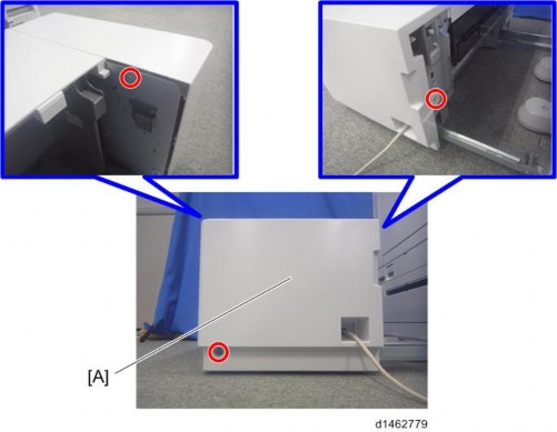
1.1 REAR COVER
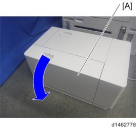
1. Pull out the LCT [A].
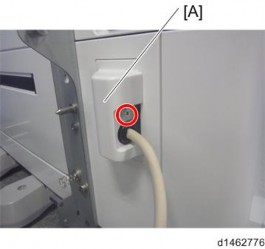
2. Cable cover [A] ![]() ×1)
×1)
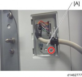
3. Cable bracket [A] ![]() ×1,
×1,![]() ×1)
×1)
4. Open the right cover [A].
Rear Cover

5. Rear cover [A] ![]() ×3)
×3)
Front Cover
LCIT RT3030 (D696)
LCIT RT3030 (D696)
LCIT RT3030 (D696)
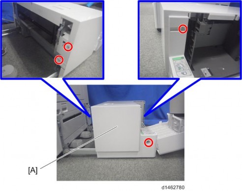
1.2 FRONT COVER
1. Open the right cover ( ![]() page 5)
page 5)
2. Front cover [A] ![]() ×4)
×4)
Upper Cover
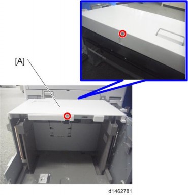
1.3 UPPER COVER
1. Front cover ![]() page 3)
page 3)
2. Rear cover ![]() page 1)
page 1)
3. Upper cover [A] ![]() ×2)
×2)
Right Cover
LCIT RT3030 (D696)
LCIT RT3030 (D696)
LCIT RT3030 (D696)
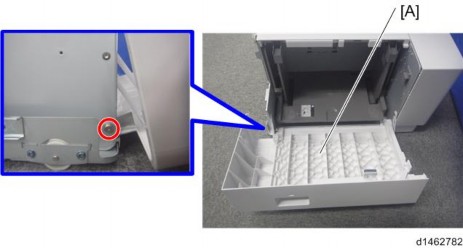
1.4 RIGHT COVER
1. Front cover ![]() page 3 )
page 3 )
2. Right cover [A] ![]() ×1,
×1,![]() ×1)
×1)
Pick-up Roller, Feed Roller, Friction Roller
1.5 PICK-UP ROLLER, FEED ROLLER, FRICTION ROLLER
1. Open the right cover.
2. Pick-up roller [A] ![]() ×1)
×1)
3. Sensor bracket [A] ![]() ×2)
×2)
4. Feed roller [A] ![]() ×1)
×1)
LCIT RT3030 (D696)
LCIT RT3030 (D696)
LCIT RT3030 (D696)
Pick-up Roller, Feed Roller, Friction Roller
5. Friction roller [A] ![]() ×1)
×1)
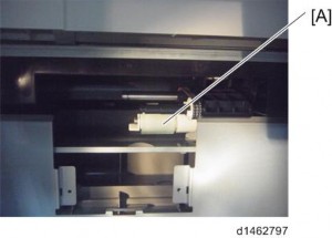
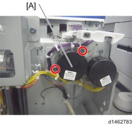
Paper Feed Motor
1.6 PAPER FEED MOTOR
1. Rear cover ![]() page 1)
page 1)
2. Paper feed motor [A] ![]() ×2,
×2, ![]() ×1)
×1)
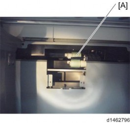
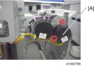
Transport Motor
LCIT RT3030 (D696)
LCIT RT3030 (D696)
LCIT RT3030 (D696)
1.7 TRANSPORT MOTOR
1. Rear cover ![]() page 1)
page 1)
2. Transport motor [A] ![]() ×2,
×2, ![]() ×1)
×1)
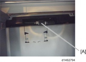
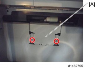
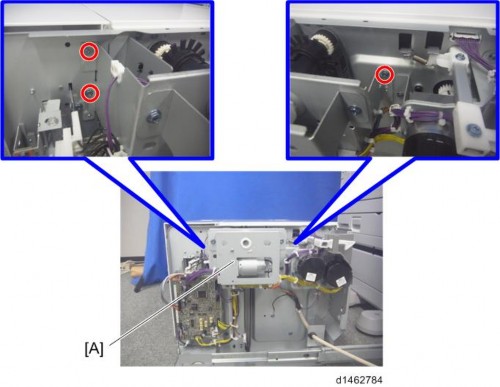
Tray Lift Unit
1.8 TRAY LIFT UNIT
1. Rear cover ![]() page 1)
page 1)
2. Tray lift unit [A] ![]() ×3,
×3, ![]() ×1,
×1, ![]() ×10)
×10)
Controller Board
LCIT RT3030 (D696)
LCIT RT3030 (D696)
LCIT RT3030 (D696)
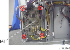
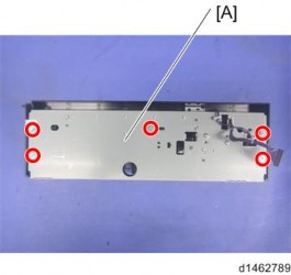
1.9 CONTROLLER BOARD
1. Rear cover ![]() page 1)
page 1)
2. Controller board [A] ![]() ×4,
×4, ![]() ×9,
×9, ![]() ×2)
×2)
LCT Set Switch (Front)
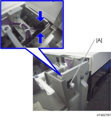
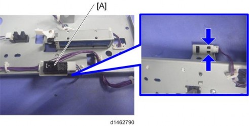
1.10 LCT SET SWITCH (FRONT)
1. Front cover ![]() page 1)
page 1)
2. LCT set switch (front) [A] ![]() ×1)
×1)
LCT Set Switch (Rear)
LCIT RT3030 (D696)
LCIT RT3030 (D696)
LCIT RT3030 (D696)
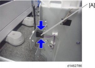
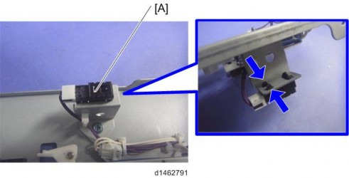
1.11 LCT SET SWITCH (REAR)
1. Front cover ![]() page 3)
page 3)
2. LCT set switch (rear) [A] ![]() ×1)
×1)
Paper Feed Sensor, Paper End Sensor, Limit Sensor, Transport Sensor
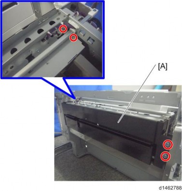
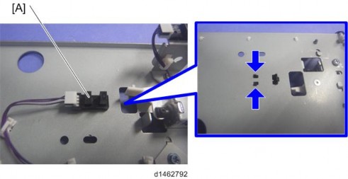
1.12 PAPER FEED SENSOR, PAPER END SENSOR, LIMIT SENSOR, TRANSPORT SENSOR
1. Upper cover ![]() page 4)
page 4)
2. Paper feed unit [A] ![]() ×2,
×2, ![]() ×1,
×1, ![]() ×2)
×2)
3. Paper feed unit cover [A] ![]() ×5)
×5)
4. Paper feed sensor [A] ![]() ×1)
×1)
LCIT RT3030 (D696)
LCIT RT3030 (D696)
LCIT RT3030 (D696)
Paper Feed Sensor, Paper End Sensor, Limit Sensor, Transport Sensor
5. Paper end sensor [A] ![]() ×1)
×1)
6. Limit sensor [A] ![]() ×1)
×1)
7. Transport sensor [A] ![]() ×1)
×1)