HOME PAGE | < Previous | Contents | Next >
SPDF DF3080 (D683)
SPDF DF3080 (D683)
SPDF DF3080 (D683)
1.1 ADF REMOVAL
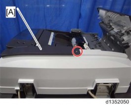
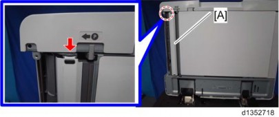
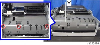
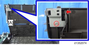
1. Controller cover [A] ![]() ×4)
×4)
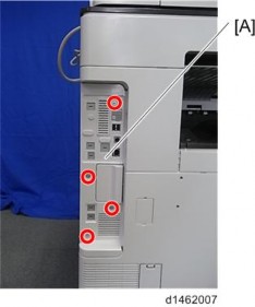
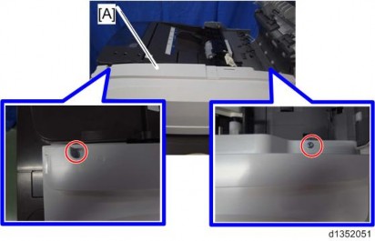
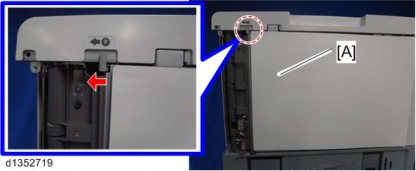
2. Rear cover [A] ![]() ×4)
×4)
3.
4.
ADF Removal
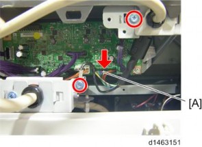
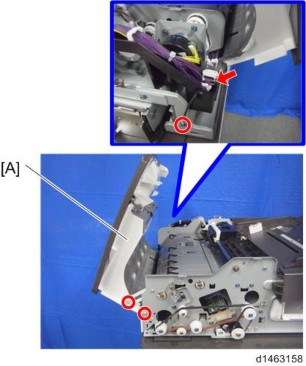
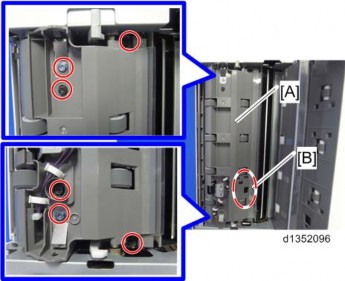
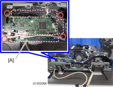
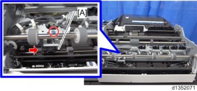
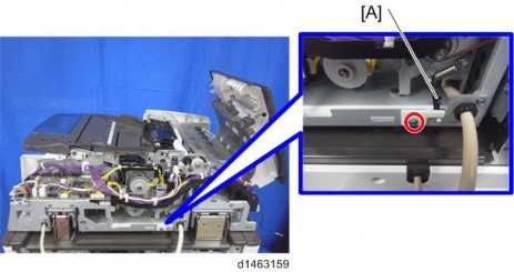
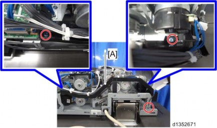
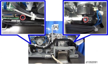
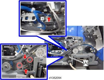
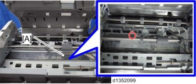
5. Disconnect the I/F cable [A] ( ×2, ×1, ×4)
6.
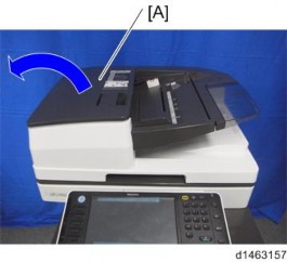
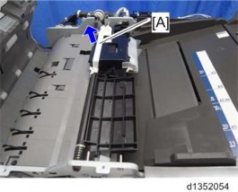
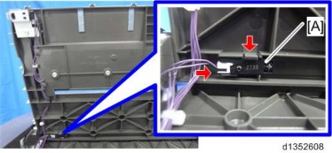
7. Open the ADF [A]
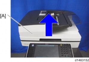
ADF Removal
SPDF DF3080 (D683)
SPDF DF3080 (D683)
SPDF DF3080 (D683)
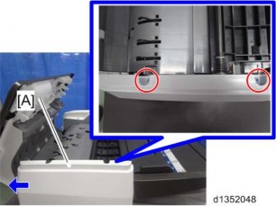
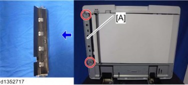
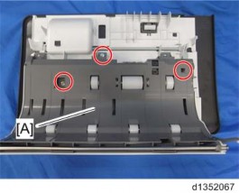
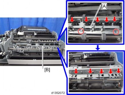
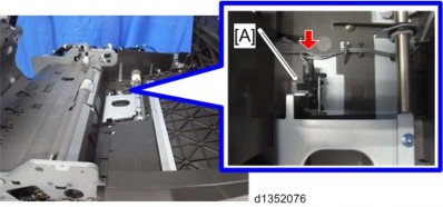
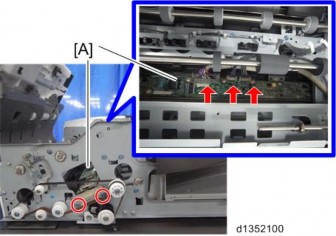
8. Remove the fixing screws of the ADF ![]() ×2)
×2)
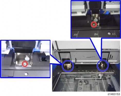
9. While holding the left and right sides of the ADF, lift up to remove it.
![]()
Because of the weight of the ADF, handle with care.
Adjustment after Replacing the ADF
1.2 ADJUSTMENT AFTER REPLACING THE ADF
1.2.1 CIS RGB ADJUSTMENT
Enter the four-digit numeric values for RGB that are listed on the paper that comes with the ADF into the following SP.
R: SP4-712-001 (CIS GB Adj Value: R) G: SP4-713-001 (CIS GB Adj Value: G) B: SP4-714-001 (CIS GB Adj Value: B)
1.2.2 CHECKING THE VERTICAL REGISTRATION
SP6-006-001 (ADF Adjustment Side-to-Side Regist: Front) SP6-006-002 (ADF Adjustment Side-to-Side Regist: Rear)
1. Create an original as shown in the following picture.
*The arrows indicate the direction of feed.
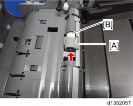
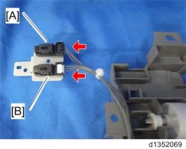
2. Copy the original and make sure that the position of the line [A] is within 0±1mm
3. If not within the standard, adjust with the SP modes.
Adjustment after Replacing the ADF
SPDF DF3080 (D683)
SPDF DF3080 (D683)
SPDF DF3080 (D683)
1.2.3 CHECKING THE HORIZONTAL REGISTRATION
SP6-006-010 (ADF Adjustment L-Edge Regist (1-Pass): Front) SP6-006-011 (ADF Adjustment L-Edge Regist (1-Pass): Rear)
1. Copy the original and make sure that the position of the line [B] is within 0±2mm.
2. If not within the standard, adjust with the SP modes.
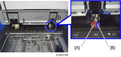
1.2.4 CHECKING THE SKEW
SP6-006-012 (ADF Adjustment 1st Buckle (1-Pass)) SP6-006-013 (ADF Adjustment 2nd Buckle (1-Pass))
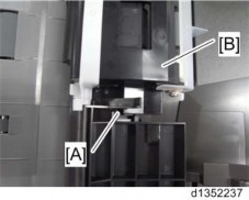
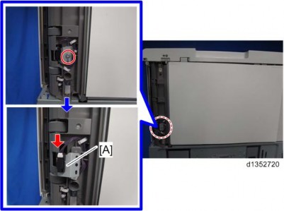
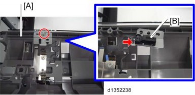
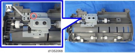
1. Make sure that the difference between both end positions of the line [A] is within 0±2mm.
2. If not within the standard, change the position of the fixing screw [A] to the long hole [B] at the right hinge.
1.2.5 CHECKING THE MAGNIFICATION
SP6-017-001 (DF Magnification Adj.)
1. Copy the original and make sure that the length of the line [B] is within 100±1mm.
2. If not within the standard, adjust with the SP mode.
Platen Adjustment
1.3 PLATEN ADJUSTMENT
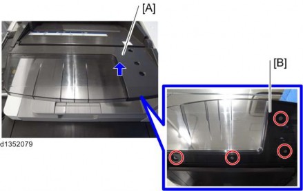
1. Open the ADF and remove the white cover (magic tape×10)
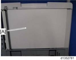
2. Put the white cover [A] in the correct position on the exposure glass, aligning it with the glass cover [B] and the rear scale [C].
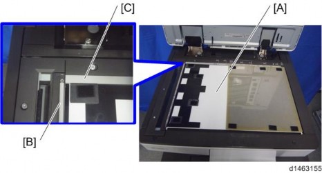
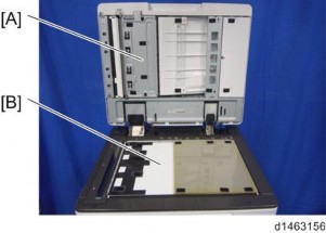
3. Close the ADF [A] slowly and paste the ADF and the white cover [B] with the magic tapes.
ADF Front Cover
SPDF DF3080 (D683)
SPDF DF3080 (D683)
SPDF DF3080 (D683)
1.4 ADF FRONT COVER
1. Open the feed cover [A].
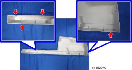
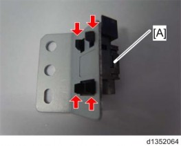
2. Slide the ADF front cover [A] to the left ![]() ×2, hook×4)
×2, hook×4)
![]()
Check the position of the hooks in the photo below before removing.
ADF Rear Cover
1.5 ADF REAR COVER
1. Open the feed cover [A].
2. Cover [A] ![]() ×1)
×1)
3. Lift off the rear cover [A] ![]() ×2, hook×4)
×2, hook×4)
![]()
Check the position of the hooks in the photo below before removing.
Feed Cover
SPDF DF3080 (D683)
SPDF DF3080 (D683)
SPDF DF3080 (D683)
1.6 FEED COVER
1. ADF front cover (page 7 "ADF Front Cover")
2. ADF rear cover (page 8 "ADF Rear Cover") 3. Feed cover [A] ![]() ×3,
×3, ![]() ×1,
×1, ![]() ×2)
×2)
Original Feed Unit
1.7 ORIGINAL FEED UNIT
1. Open the feed cover.
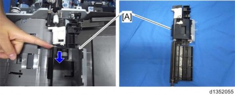
2. Remove the snap-fit [A].
3. Original feed unit [A] (Pull the original feed unit, remove the back side of the shaft. Then, remove the bushing in the foreground.)
Pick-up Roller / Transport Belt
SPDF DF3080 (D683)
SPDF DF3080 (D683)
SPDF DF3080 (D683)
1.8 PICK-UP ROLLER / TRANSPORT BELT
1. Original feed unit (page 10 "Original Feed Unit")
2. Slide the resin bushing [A], and then remove the pick-up roller unit [B].
![]()
At re-assembly, make sure that the tab on the front guide plate [A] is above the pick-up roller [B].
3. Pick-up roller cover [A] and pick-up roller [B] ![]() ×2, bushing×2, one-way clutch×1)
×2, bushing×2, one-way clutch×1)
Pick-up Roller / Transport Belt
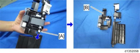
4. Lift the left and right sides of the feed belt holder [A], then remove it.
5. Remove the feed belt [B] from the feed belt holder [A].
ADF Separation Roller
SPDF DF3080 (D683)
SPDF DF3080 (D683)
SPDF DF3080 (D683)
1.9 ADF SEPARATION ROLLER
1. Open the feed cover.
2. Original feed unit (page 10 "Original Feed Unit")
3. ADF separation roller cover [A].
4. ADF separation roller [A] and torque limiter clutch [B] ![]() ×1)
×1)
Original Registration Sensor
1.10 ORIGINAL REGISTRATION SENSOR
1. Entrance lower guide [A] ![]() ×2)
×2)

2. Scanning guide plate [A] (hook×1)

3. Original registration sensor [A] along with the bracket ![]() ×1,
×1, ![]() ×1)
×1)
Original Registration Sensor
SPDF DF3080 (D683)
SPDF DF3080 (D683)
SPDF DF3080 (D683)
4. Original Registration Sensor [A] (hook×4)
Original Exit Sensor
1.11 ORIGINAL EXIT SENSOR
1. Entrance lower guide [A] ![]() ×2)
×2)
2. Scanning guide plate [A] (hook×1)
3. Open the white cover [A].
4. Remove the original exit sensor [B], which is mounted on the upper guide [A] ![]() ×6)
×6)
SPDF DF3080 (D683)
SPDF DF3080 (D683)
SPDF DF3080 (D683)
Original Exit Sensor
5. Remove the original exit sensor [B] from the upper guide [A] ![]() ×1,
×1, ![]() ×1)
×1)
ADF Control Board
1.12 ADF CONTROL BOARD
1. ADF rear cover (page 8 "ADF Rear Cover")
2. ADF control board [A] ![]() ×4, all
×4, all ![]() s)
s)
Separation Sensor / Skew Correction Sensor
SPDF DF3080 (D683)
SPDF DF3080 (D683)
SPDF DF3080 (D683)
1.13 SEPARATION SENSOR / SKEW CORRECTION SENSOR
1. Feed upper guide [A] in the feed cover ![]() ×3)
×3)
2. Remove the sensors along with the bracket [A] ![]() ×1)
×1)
3. Separation Sensor [A] and Skew Correction Sensor [B] ![]() ×1 each)
×1 each)
Original Width Sensor / Interval Sensor
1.14 ORIGINAL WIDTH SENSOR / INTERVAL SENSOR
1. Feed cover (page 9 "Feed Cover")
2. Guide plate [A] ![]() ×3)
×3)
3. Interval sensor [A] ![]() ×1,
×1, ![]() ×1)
×1)
4. Remove the original width sensor guide plate [A] ![]() ×2), then remove the original width sensors
×2), then remove the original width sensors ![]() ×5) [B] (hook×1 each)
×5) [B] (hook×1 each)
B5 Width Sensor / A4 Width Sensor / LG Width Sensor
SPDF DF3080 (D683)
SPDF DF3080 (D683)
SPDF DF3080 (D683)
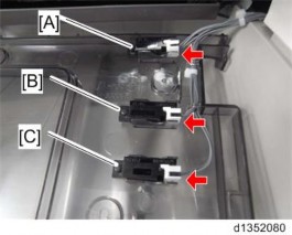
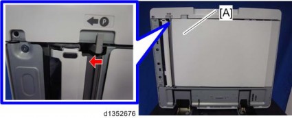
1.15 B5 WIDTH SENSOR / A4 WIDTH SENSOR / LG WIDTH SENSOR
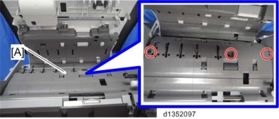
1. Raise the document tray [A], then remove the lower cover [B] ![]() ×4)
×4)
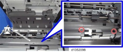
2. B5 Width Sensor [A] ![]() ×1)
×1)
3. A4 Width Sensor [B] ![]() ×1)
×1)
4. LG Width Sensor[C] ![]() ×1)
×1)
APS Feeler
1.16 APS FEELER
1. ADF rear cover (page 8 "ADF Rear Cover")
2. APS Feeler [A] ![]() ×1)
×1)
ADF Lift-Up Interlock SW / Lift-Up Sensor
SPDF DF3080 (D683)
SPDF DF3080 (D683)
SPDF DF3080 (D683)
1.17 ADF LIFT-UP INTERLOCK SW / LIFT-UP SENSOR
1. ADF Control Board (page 18 "ADF Control Board")
2. ADF lift-up interlock SW [A] along with the bracket ![]() ×3,
×3, ![]() ×2)
×2)
3. Lift-Up Sensor [A] along with the bracket ![]() ×1,
×1, ![]() ×1)
×1)
Original Set Sensor
1.18 ORIGINAL SET SENSOR
1. ADF front cover (page 7 "ADF Front Cover")
2. Remove the screw and raise the original tray [A] ![]() ×1)
×1)
3.
A4 LEF/LT LEF Sensor
SPDF DF3080 (D683)
SPDF DF3080 (D683)
SPDF DF3080 (D683)
1.19 A4 LEF/LT LEF SENSOR
1. ADF front cover (page 7 "ADF Front Cover")
2. Remove the screw and raise the original tray [A] ![]() ×1)
×1)
3. A4 LEF/LT LEF Sensor [A] (hook×1, ×1)
Bottom Plate HP Sensor
1.20 BOTTOM PLATE HP SENSOR
1. Original feed unit (page 10 "Original Feed Unit")
2. ADF front cover (page 7 "ADF Front Cover")
3. Remove the screw and raise the original tray [A] ![]() ×1)
×1)
4.
Bottom Plate Position Sensor
SPDF DF3080 (D683)
SPDF DF3080 (D683)
SPDF DF3080 (D683)
1.21 BOTTOM PLATE POSITION SENSOR
1. ADF rear cover (page 8 "ADF Rear Cover")
2. Original feed unit (page 10 "Original Feed Unit")
3. Bottom plate position sensor [A] ![]() ×1)
×1)
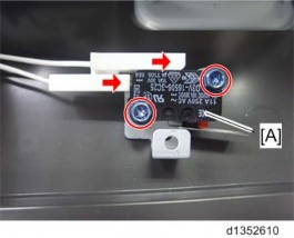
ADF Feed Cover Interlock Switch / Pick-up Roller HP Sensor
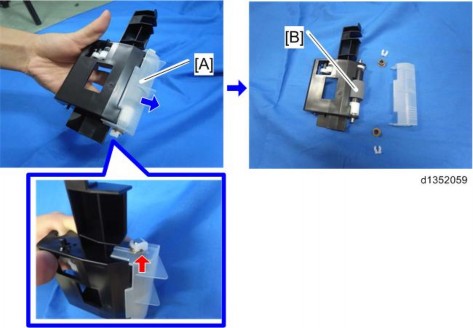
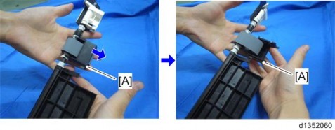
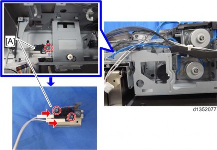
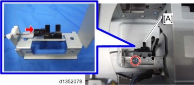
1.22 ADF FEED COVER INTERLOCK SWITCH / PICK-UP ROLLER HP SENSOR
1. ADF rear cover (page 8 "ADF Rear Cover")
2. Remove the ADF feed cover interlock switch [A] from the retaining bracket ![]() ×1, spring×1, pin×1)
×1, spring×1, pin×1)
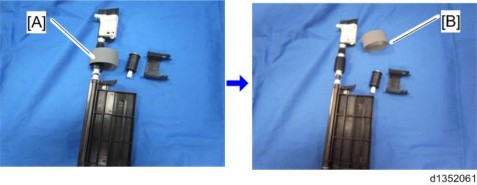
3. ADF feed cover interlock switch [A] ![]() ×2,
×2, ![]() ×2)
×2)
4. Pick-up roller HP sensor [A] along with the bracket ![]() ×1,
×1, ![]() ×1,
×1, ![]() ×1)
×1)
SPDF DF3080 (D683)
SPDF DF3080 (D683)
SPDF DF3080 (D683)
ADF Feed Cover Interlock Switch / Pick-up Roller HP Sensor
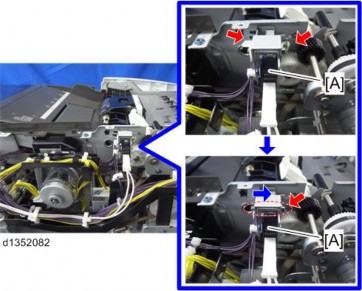
ADF Entrance Motor
1.23 ADF ENTRANCE MOTOR
1. ADF rear cover (page 8 "ADF Rear Cover")
2. ADF entrance motor [A] along with the frame ![]() ×2,
×2, ![]() ×2,
×2, ![]() ×2, spring×1, timing belt×1)
×2, spring×1, timing belt×1)
3.
ADF Scanning Motor
SPDF DF3080 (D683)
SPDF DF3080 (D683)
SPDF DF3080 (D683)
1.24 ADF SCANNING MOTOR
1. ADF entrance motor along with the frame (page 30 "ADF Entrance Motor")
2. ADF read motor [A] along with the bracket ![]() ×2,
×2, ![]() ×1 , spring×1, timing belt×1)
×1 , spring×1, timing belt×1)
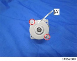
3. ADF scanning motor [A] ![]() ×2)
×2)

ADF Exit Motor
1.25 ADF EXIT MOTOR
1. ADF Control Board (page 18 "ADF Control Board")
2. ADF exit motor [A] along with the bracket ![]() ×2,
×2, ![]() ×1, spring×1, timing belt×1)
×1, spring×1, timing belt×1)
3. ADF exit motor [A] ![]() ×3)
×3)
ADF Bottom Plate Lift Motor
SPDF DF3080 (D683)
SPDF DF3080 (D683)
SPDF DF3080 (D683)
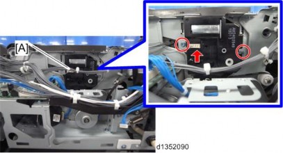
1.26 ADF BOTTOM PLATE LIFT MOTOR
1. ADF entrance motor along with the frame (page 30 "ADF Entrance Motor")
2. ADF bottom plate lift motor [A] ![]() ×2,
×2, ![]() ×1)
×1)
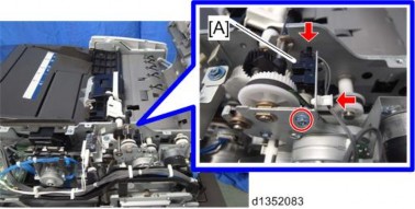
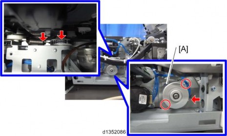
ADF Pick-up Roller Lift Motor / ADF Transport Motor
1.27 ADF PICK-UP ROLLER LIFT MOTOR / ADF TRANSPORT MOTOR
1. ADF rear cover (page 8 "ADF Rear Cover")
2. Frame (black) [A] ![]() ×3)
×3)
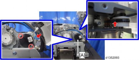
3. ADF pick-up roller lift motor [A] ![]() ×2,
×2, ![]() ×1, timing belt×1)
×1, timing belt×1)
4. ADF transport motor [A] along with the bracket ![]() ×2,
×2, ![]() ×1, timing belt×1)
×1, timing belt×1)
SPDF DF3080 (D683)
SPDF DF3080 (D683)
SPDF DF3080 (D683)
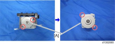
ADF Pick-up Roller Lift Motor / ADF Transport Motor
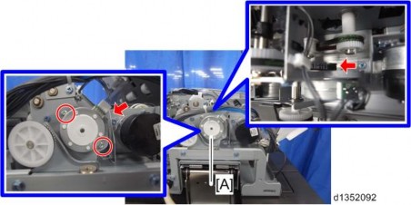
5. ADF transport motor [A] ![]() ×3)
×3)

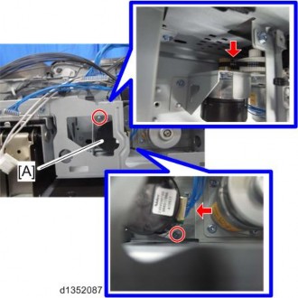
ADF Feed Motor
1.28 ADF FEED MOTOR
1. ADF rear cover (page 8 "ADF Rear Cover")
2. Remove the fixing screws of the frame (black) [A] ![]() ×2).
×2).
3. ADF entrance motor along with the frame (page 30 "ADF Entrance Motor")
4. ADF feed motor [A] along with the bracket ![]() ×2,
×2, ![]() ×1, spring×1, timing belt×1)
×1, spring×1, timing belt×1)
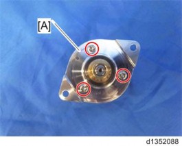
ADF Feed Motor
SPDF DF3080 (D683)
SPDF DF3080 (D683)
SPDF DF3080 (D683)
5. ADF feed motor [A] ![]() ×2)
×2)
CIS Unit
1.29 CIS UNIT
1. Original Feed Unit (page 10 "Original Feed Unit")
2. ADF Separation Roller (page 13 "ADF Separation Roller")
3. ADF front cover (page 7 "ADF Front Cover")
4. Guide plate (large) [A] ![]() ×3)
×3)
5. Guide plate (small) [A] ![]() ×2)
×2)
6. Guide plate [A] ![]() ×1)
×1)
7. CIS unit [A] ![]() ×2,
×2, ![]() ×3)
×3)
SPDF DF3080 (D683)
SPDF DF3080 (D683)
SPDF DF3080 (D683)
CIS Unit
![]()
To prevent scratches on the surface of the CIS glass, removal of the CIS unit must be done with the white cover [A] open.
REVISION H IST ORY | ||
Page | Date | Added/ Updated/ New |
None | ||
REVISION H IST ORY | ||
Page | Date | Added/ Updated/ New |
None | ||
REVISION H IST ORY | ||
Page | Date | Added/ Updated/ New |
None | ||