HOME PAGE | < Previous | Contents | Next >
![]()
The optional handset is available for the U.S. version only.
1. Open the front cover.
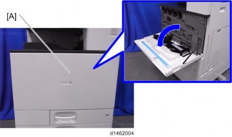
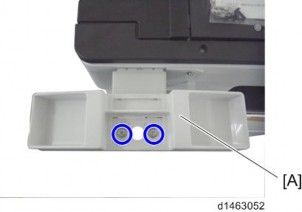
2. Remove the paper exit tray [A].
3.
Slide the cover in the direction of the blue arrow.
4.
5.
6.
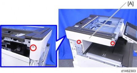
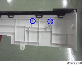
7. Make two holes in the scanner left cover.
8. Reattach the scanner left cover ![]() x 3).
x 3).
9. Re-assemble the machine.
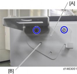
10. Attach the bracket [A] enclosed with the fax unit ![]() x 2: M3 x 12) as shown.
x 2: M3 x 12) as shown.
Only for the machine with the single pass ADF, use the hole [B] to tilt the bracket.
11. Attach the cradle [A] to the handset bracket ![]() x 2).
x 2).
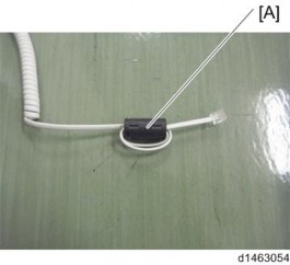
12. Attach the ferrite core [A] to the cable.
13. Connect the cable to the "TEL" jack on the left side of the controller box.