HOME PAGE | < Previous | Contents | Next >
1.4 G3 INTERFACE UNIT TYPE M3 (D163)
This G3 interface unit option is used only for Fax Option Type M3 (D163) models.
1.4.1 COMPONENT CHECK
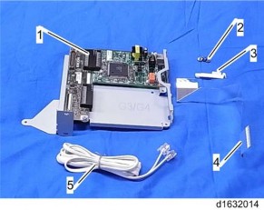
Check the quantity and condition of the components against the following list.
No. | Description | Q'ty |
1 | SG3 Interface Unit | 1 |
2 | Screw: M3x6 | 3 |
3 | Harness Clamp | 2 |
4 | Flat Cable | 1 |
5 | Telephone Cable (NA only) | 1 |
- | Ferrite Core | 1 |
- | EMC Address Decal (EU only) | 1 |
- | FCC Decal (NA only) | 1 |
1.4.2 INSTALLATION PROCEDURE
![]()
Before installing this optional unit:
Print out all data in the printer buffer.
Turn off the main switch and disconnect the power cord and the network cable.
You can add two more SG3 boards to this model. Follow the procedures for adding the single SG3 board installation or double SG3 board installation as the customer needs.
For Installing the single G3 Board
1. If the FCU is not installed in the machine, install the FCU (D163) in the machine first (page 7 "Fax Option Type M3 (D163)").
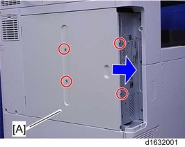
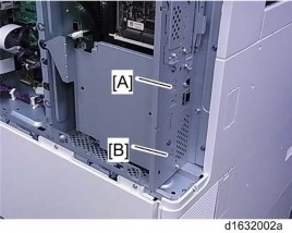
2. Remove the controller box cover [A] ![]() x 4).
x 4).

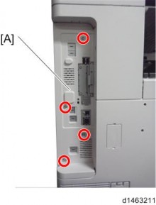
3. Remove the rear cover [A] ![]() x 4).
x 4).
4. Remove the "TEL2" [A] cover with a screw driver.
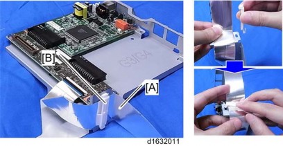
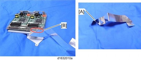
5. Attach one end [A] of the flat cable to CN660 on the CCU I/F board of the SG3 interface unit.
Make sure that the blue tape of the flat cable faces outward.
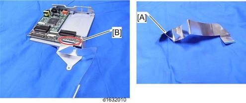
6. Attach the flat cable [A] to the bracket of the SG3 interface unit with the clamp [B].
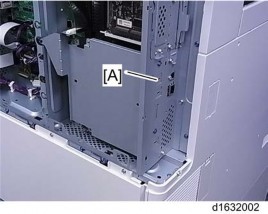
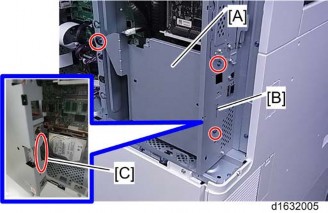
7. Install the SG3 interface unit [A] ![]() x 3).
x 3).
Insert the tab [B] of the controller box in the cutout [C] of the SG3 interface unit.
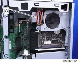
8. Connect the other end [A] of the flat cable to CN603 on the FCU board.
9. Reinstall the rear cover and controller box cover.
10. Attach the ferrite core to the telephone cord for single SG3 board installation.
11. Connect the telephone cord to the "LINE 2" jack for single SG3 board installation.
12. Connect the power plug to a power outlet and turn on the main power switch.
13. Enter the service mode. Set bit 1 of communication switch 16 to "1" (SP1-104-023).
14. Exit the service mode.
15. Turn the main power switch off and on.
16. Print out the system parameter list. Then check that "G3" shows as an option.
17. Set up and program the items required for PSTN-2 communications.
For Installing the Double G3 Boards
1. If the FCU is not installed in the machine, install the FCU (D163) in the machine first (page 7 "Fax Option Type M3 (D163)").
2. Remove the controller box cover [A] ![]() x 4).
x 4).
3. Remove the rear cover [A] ![]() x 4).
x 4).

4. Remove the "LINE2" [A] and "LINE3" [B] covers with a screw driver.
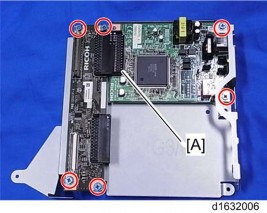
5. Remove the CCU I/F board and SG3 board [A] from the SG3 interface unit ![]() x 6).
x 6).
Do the same procedure as shown above for the second SG3 interface unit.
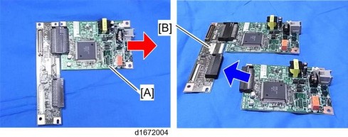
6. Remove the SG3 board [A] from one of the CCU I/F and SG3 board assemblies that you removed in step 5.
7. Attach the SG3 board removed in step 6 to the other CCU I/F and SG3 board assembly [B].
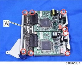
8. Attach the boards (CCU I/F board and two SG3 boards) to the SG3 interface unit bracket ![]() x 8).
x 8).
Use two screws from the six screws that were removed in step 5.
9. Attach one end [A] of the flat cable to CN660 [B] on the CCU I/F board of the SG3 interface unit.
Make sure that the blue tape of the flat cable faces outward.
10. Attach the flat cable [A] to the bracket of the SG3 interface unit with the clamp [B].
Make sure that the blue tape of the flat cable faces outward.
11.
Insert the tab [B] of the controller box in the cutout [C] of the SG3 interface unit.

12. Connect the other end [A] of the flat cable to CN603 on the FCU board.

13. Reinstall the rear cover and controller box cover.
14. Attach the two ferrite cores to the telephone cords for double-SG3 board installation.
15. Connect the telephone cords to the "LINE2" and "LINE3" jacks.
16. Connect the power plug to a power outlet and turn on the main power switch.
17. Enter the service mode. Set bit 1 of communication switch 16 to "1" (SP1-104-023).
18. Set bit 3 of communication switch 16 to "1" (SP1-104-023).
19. Exit the service mode.
20. Turn the main power switch off and on.
21. Print out the system parameter list. Then check that "G3" shows as an option.
22. Set up and program the items required for PSTN-2 communications.