HOME PAGE | < Previous | Contents | Next >
![]()
Before installing this fax unit:
Print out all data in the printer buffer.
Turn off the main power switch and disconnect the power cord and the network cable.
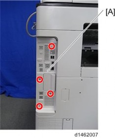
1. Remove the controller box cover [A] ![]() x 4).
x 4).
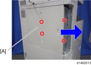
2. Remove the rear cover [A] ![]() x 4).
x 4).
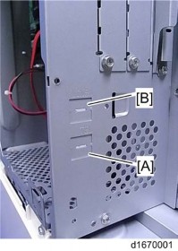
3. Remove the "TEL" [A] and "LINE1" [B] covers with a screw driver.
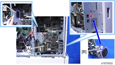
4. Install the FCU [A] on the controller ![]() x 2).
x 2).
Insert the tab [B] of the FCU bracket in the cutout on the left of the controller box.
Make sure that both connectors [C] are connected.
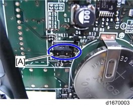
5. Switch the battery jumper switch [A] to the "ON" position.
![]()
If you don‘t switch the battery jumper switch position, SC820 will occur.
6. Reinstall the rear cover and controller box cover.
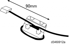
7. Attach the handset support bracket and handset bracket to the copier, and then connect the handset cord with the ferrite core to the "TEL" jack if you install the handset to the machine.
![]()
For details, refer to "Handset Installation" in the Service Manual for the Fax Unit (D167).
8. Attach the ferrite core to the telephone cord.
9. Connect the telephone cord to the "LINE 1" jack.
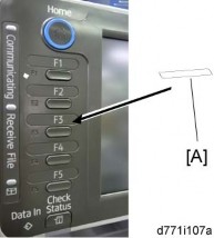
10. Attach the fax key decal [A] to the third key top from bottom.
11. Attach the serial number decal under the copier serial number decal on the rear cover of the machine.