HOME PAGE | < Previous | Contents | Next >
SMART OPERATION PANEL TYPE M3 (D148)
SMART OPERATION PANEL TYPE M3 (D148)
SMART OPERATION PANEL TYPE M3 (D148)
4.1.5 SELF-DIAGNOSIS
The following menus can be performed as self-diagnosis functions of the control unit. Either Japanese or English can be displayed.
1. LED Check
The following control unit LED can be changed over between all on/all off.
Data in
USB access
HOME
Status check (When lit, R->G->B->R->G->B is repeated at 500 ms intervals)
BACK/MENU
FAX
SD access
2. Key check
Check pressing hard keys other than the [HOME] key on the control unit. When a key is depressed, the corresponding key displayed on the control unit is shown highlighted.
If a foot switch is fitted, while the switch is depressed, the "FOOT SW" column is highlighted. When the [End] key is depressed, the display returns to the self-diagnosis top screen (the Return key works as a key check, so it cannot be used as a key to return to the self-diagnosis top screen).
3. LCD Check
System Maintenance
Whenever the screen is touched, the display cycles through All-white -> All-black -> All-green
-> All-blue -> End in full screen view, and the display status of each color is visually verified. By cycling through all the colors, the LCD check is completed, and the display returns to the self-diagnosis top screen.
4. Speaker check
The following standard sounds are generated according to the button instructions on the screen.
Frequency: 220 Hz, 440 Hz, 880 Hz, 1760 Hz, 2000 Hz
Sound volume: 16 levels from minimum to maximum
Sounds standard sound by START/STOP toggle switch
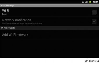
5. Wireless LAN check
Changes to a screen for searching wireless LAN access points with Android as standard, and a communication status check is displayed.
SMART OPERATION PANEL TYPE M3 (D148)
SMART OPERATION PANEL TYPE M3 (D148)
SMART OPERATION PANEL TYPE M3 (D148)
System Maintenance
6. Touch panel check
Displays the difference of a detection coordinate value from the nearest reference point relative to a standard 9 points on the screen.
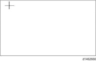
7. Touch panel calibration
Perform a touch-panel calibration, and set a value.
One + mark after another is displayed at locations (5 points) required for calibration. Press the center point.
When input of 5 points is complete, a display for set/reset appears.
OK: Press Menu key
Retry: Press Back key
System Maintenance
When it is desired to set the current value, the operation is completed by pressing the "Menu" key, and the display returns to the self-diagnosis screen.
To repeat the setting, or to stop touch panel calibration, press the Return key.
When the Return key is pressed, a + mark is displayed in the first position for performing calibration.
When this display appears, by pressing the Return key again, the display returns to the self-diagnosis screen.