HOME PAGE | < Previous | Contents | Next >
2.2.3 INSTALLATION PROCEDURE
![]()
Remove the tape from the development units before you turn the main switch on. The development units can be severely damaged if you do not remove the tape.
Installation
Installation
Installation
Put the machine on the paper tray unit or the LCT first if you install an optional paper tray unit or the optional LCT at the same time. Then install the machine and other options.
![]()
Keep the shipping retainers after you install the machine. You may need them in the future if you transport the machine to another location.
Removal of packing materials and shipping retainers / Removal of PCDU seal
1. Remove the machine from the box, and check the items in the package.
![]()
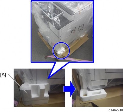
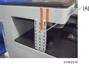
Before lifting up the machine, as there are hidden handles, remove the retainers [A] at the lower front right.
![]()
When you lift the machine, hold the correct parts, as shown in the diagram below.
Do not lift by holding the scanner unit, etc., because this might deform the machine or break the exterior covers
Main Machine Installation
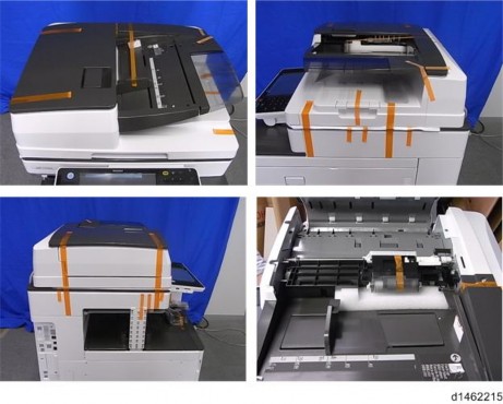
2. Remove the orange tape and retainers on the outside.
For a machine with preinstalled SPDF, remove the orange tape and retainers on the SPDF.
![]()
Make sure to remove the cardboard stabilizer shown below. If you do not, JAM 27 or JAM 64 may occur when printing out onto B4, DLT, or SRA3 sized paper in duplex mode.
D146/D147/D148/D149/D150 2-8 SM
Main Machine Installation
Installation
Installation
Installation
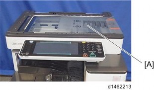
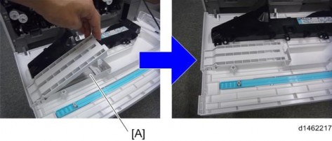
3. Remove the paper size decal [A] on the exposure glass.
4. Pull out the 1st paper feed tray, and remove the orange tape and retainers.
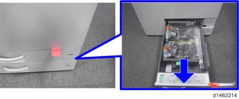
5. Pull out the 2nd paper feed tray, and remove the orange tape and retainers.
6. Remove the scanner support [A].
Main Machine Installation
7. Open the front cover, and store the scanner support in the storage location [A].
![]()
The factory setting sheet is kept in the position [A].
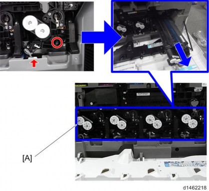
8. Remove the PCDU [A]. ![]() ×4,
×4,![]() ×4)
×4)
Main Machine Installation
Installation
Installation
Installation
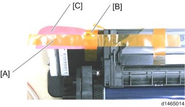
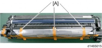
9. After removing the orange tape [A], remove the orange tape [B] and red tag [C].
10. Remove the orange tapes [A].
![]()
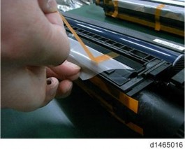
When removing the orange tapes, remove the orange tapes one by one without removing the preset seal as shown below.
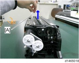
11. Remove the preset seal [A] in the direction of the blue arrow.
Main Machine Installation
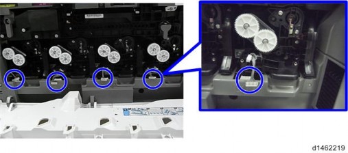
12. Return the PCDU to its original position, and connect the harnesses (4 for each unit).
![]()
When you return the PCDU to its original position, check the color (engraving), and set each color unit in the right position.
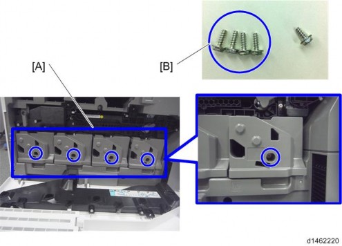
13. Attach the PCDU front cover [A] with the screws provided (3×10) [B]. ( ![]() ×4)
×4)
Main Machine Installation
![]()
Installation
Installation
Installation
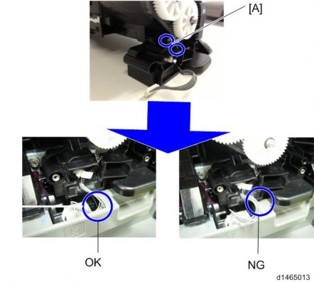
Be careful not to trap the harness with the PCDU front cover. Place the excess portion of the harness on the inside of the inner cover. Also, hook the harness in two places [A].
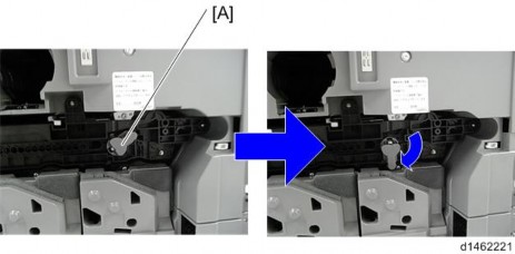
14. Rotate the ITB contact/separation lever [A] clockwise, and set it to the position in the following picture.
15. Attach the ITB unit front cover [A] with the screw provided (3×8) [B].