HOME PAGE | < Previous | Contents | Next >
4.15.7 BY-PASS TRAY SIDE FENCE (D150 ONLY)
When replacing the side fence (including the Hall element), be sure to perform steps 1-7, and when replacing or disassembling other parts, be sure to perform steps 5-7.
1. Input the following output values into SP mode.
Input the output value from SP5-803-087 (INPUT Check SI Bypass SF Paper Contact Sensor: Front) to SP1-008-007 (SI By-Pass Size Detection Adj Sidefence F adj2).
Input the output value from SP5-803-088 (INPUT Check SI Bypass SF Paper Contact Sensor: Rear) to SP1-008-009 (SI By-Pass Size Detection Adj Sidefence R adj2).
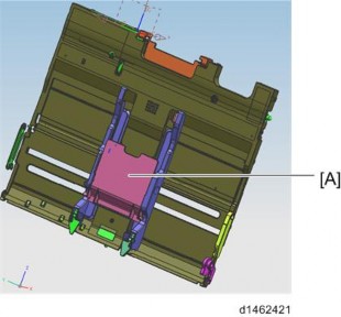
2. Remove the extension tray [A] of the by-pass tray, make the side fence slightly wider than the width of the extension tray, and set it in the by-pass tray as follows.
3. When the extension tray is set, switch SP5-804-087 (OUTPUT Check SI Bypass SF Drive Motor:CCW (500pps)) ON, and move the side fence inside until it contacts the extension tray and can no longer move.
4. When the side fence is in contact with the extension tray, input the following output values into SP mode.
Input the output value from SP5-803-087 (INPUT Check SI Bypass SF Paper Contact Sensor: Front) to SP1-008-006 (SI By-Pass Size Detection Adj Sidefence F adj1).
Input the output value from SP5-803-088 (INPUT Check SI Bypass SF Paper Contact Sensor: Rear) to SP1-008-008 (SI By-Pass Size Detection Adj Sidefence R adj1).
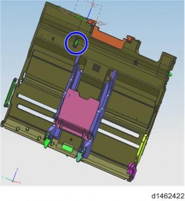
5. While holding the feeler of the By-pass length sensor with your hand, perform SP1-008-032 (SI By-Pass Size Detection Adj Main Scan Size Adj). When the auto-adjusting SP starts, release the feeler (the SP value of each paper size is read automatically, and stored).
By-pass Tray Unit
6. When the side fence starts to move towards the outside, remove the extension tray.
Replacement and Adjustment
Replacement and Adjustment
Replacement and Adjustment
7. Check SP1-008-033 (SI By-Pass Size Detection Adj Main Scan Size Adj Result), and check that it is 1: Succeed.