HOME PAGE | < Previous | Contents | Next >
7. Close the left cover.
8. Plug in and turn on the main power switch.
9. Set SP2-109-003 to 1, press ‘Copy Window’, and print. The 1-dot vertical line test pattern is printed.
After outputting the 1-dot vertical line pattern, set SP2-109-003 to "0."
Replacement and Adjustment
Replacement and Adjustment
Replacement and Adjustment
Check that the space on either side is less than 4±1 mm. If it is not within these limits, change the reference value of the main scanning magnification adjustment (SP4-011-001).
10. Perform line adjustment.
SP2-111-004: Forced Line Position Adj. Mode d
The result can be checked with SP2-194-007 (MUSIC Execution Result Execution Result) (0: Succeed, 1: Fail).
Also, results for each color can be checked with SP2-194-010 to 013.
11. Exit the SP mode.
4.7.2 POLYGON MOTOR
1. Polygon motor cover (page 4-52 "Laser Unit")
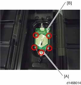
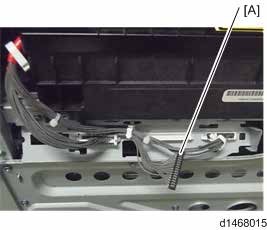
2. Polygon motor holder [A], Polygon motor [B] ![]() ×5,
×5, ![]() ×1)
×1)