HOME PAGE | < Previous | Contents | Next >
Scanner Wire Assembly (rear side)
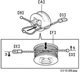
1. Pull the scanner wire ball end [B] to the pulley [A] from the right side of the pulley as shown in the diagram.
2. Set the ball [C] in the center part of the wire on the pulley.
Replacement and Adjustment
Replacement and Adjustment
Replacement and Adjustment
3. Turn the ball end [D] 4.5 times clockwise along the edge on the rear side of the pulley.
4. Turn the ring end [E] 3.5 times counterclockwise along the edge at the front side of the pulley.
5. Check that the blue marks [F] of the wire overlap, and secure it temporarily with Teflon tape, etc.
6. Set the pulley on the drive shaft, and attach the scanner drive gear.
7. Attach the scanner wire on the rear side as in Step 7, attaching the scanner wire (front side).
4.6.11 MODIFYING THE SCANNER (CONTACT/CONTACTLESS) WHEN USING ARDF
Procedure for the ADF
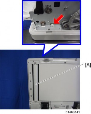
1. ADF front cover [A] ![]() ×1)
×1)
![]()
Remove with the document table [B] lifted up.
2.
Scanner Unit
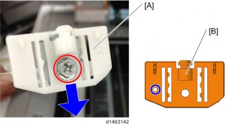
3. Replace the contactless guide plate (front) [A] with the contact guide plate (front) [B]. ![]() ×1) There is a hole in the contact guide plate (front).
×1) There is a hole in the contact guide plate (front).
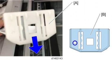
4. Replace the contactless guide plate (rear) [A] with the contact guide plate (rear) [B]. There is a hole in the contact guide plate (rear).
Scanner Unit
Replacement and Adjustment
Replacement and Adjustment
Replacement and Adjustment
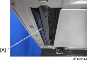
5. Attach the document reader guide plate. Be careful not to scratch the sheet [A].
6. Attach the ADF front cover, and return the ADF to its original position.
7. From the SP mode, change the DF density setting (SP4-688-001) from [106%] to [101%].