HOME PAGE | < Previous | Contents | Next >
2.20 PUNCH UNIT PU3040
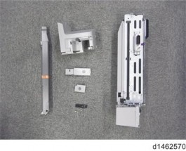
2.20.1 ACCESSORY CHECK
Description | Q’ty |
Tapping screws - M3x 6 | 3 |
Decal - EMC Address | 1 |
Knob Screw - M4 | 1 |
Hopper | 1 |
Holder | 1 |
Punch Unit Cover | 1 |
Lower Front Cover | 1 |
Lower Rear Cover | 1 |
2.20.2 INSTALLATION PROCEDURE
![]()
When installing this option, turn the power to the machine off, and unplug the power plug from the wall socket.
If it is installed when the power is on, it will result in an electric shock or a malfunction.
![]()
When supplied together with the “Internal Finisher SR3130”, attach this option before installing the “Internal Finisher SR3130”
If the “Internal Finisher SR3130” is already attached, attach this option after removing the
Punch Unit PU3040
finisher.
1. Take out from the box, and remove the filament tape and packing material.
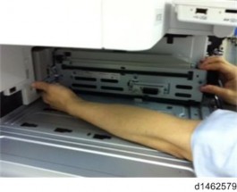
2. Remove the finisher and finisher front right cover from the machine.
3. Perform steps 1 to 17 of the installation procedure for the "Internal finisher SR3130".
Installation
Installation
Installation
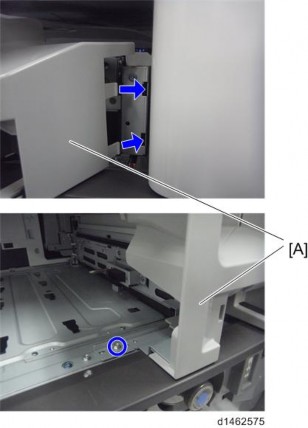
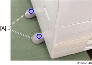
4. Change the fixing position of the bracket [A] of the bottom plate ![]() ×1).
×1).
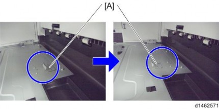
5. Replace the lock holder of the bottom plate with the lock holder [A] provided ![]() ×1).
×1).
6. Attach the main power switch cover.
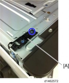
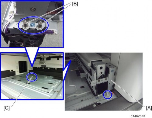
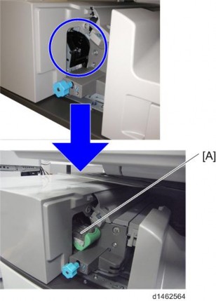
7. Pass the shafts [B] of the punch unit [A] through the bearings [C] of the bottom plate, and attach to the machine ![]() ×1, knob screw).
×1, knob screw).
If it is difficult to insert by probing, look from the side while you insert it into the bearings of the bottom plate.
Punch Unit PU3040
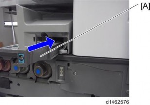
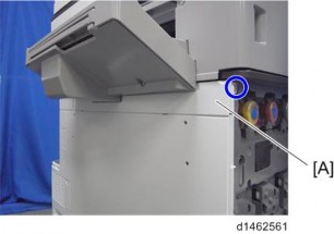
8. When installing the punch unit in a finisher that is already installed, remove the relay guide plate [A] ![]() ×2).
×2).
This step is unnecessary when installing the finisher and punch unit at the same
Punch Unit PU3040
time.
Installation
Installation
Installation
9. Attach the front right cover [A] provided, inserting the claws ![]() ×1).
×1).
10. Insert the hopper [A].
11. Slide the finisher [A] along the rail of the bottom plate from the left-hand side of the machine to attach it ![]() ×1).
×1).
Punch Unit PU3040
12. Attach the components [A] and [B] to the finisher ![]() ×2).
×2).
13. Attach the left rear cover
14. Insert the upper left cover [A] from the front, and slide it to attach it.
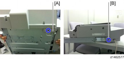
15. Attach stabilizers [A].
![]()
Because the weight is biased to the right of the machine if the inner finisher is installed, anti-tip components are required on the left side. Because they are included with the finisher, install these components at the same time as you install the inner finisher.
Punch Unit PU3040
Installation
Installation
Installation
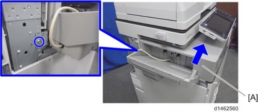
16. Connect the interface cable to the machine.
![]()
.
17. Move forward the stapler unit, then set the stapler [A].
18. Turn the power switch on.
19. Check that the finisher can be selected at the operation panel, and check the finisher and punch operation.