HOME PAGE | < Previous | Contents | Next >
2.19.2 INSTALLATION PROCEDURE
![]()
Removal of stabilizers must always be with the consent of the customer. Do not remove them at your own judgment.
When you install this option, turn off the power to the machine, and unplug the power plug from the wall socket.
If it is installed with the power on, it will result in an electric shock or a malfunction.
![]()
Cannot be used together with “Internal Shift Tray SH3070”, “Side Tray Type M3”, “Bridge Unit BU3070”, “Finisher SR3140”, “Booklet Finisher SR3150”, “Finisher SR3160”, “Booklet Finisher SR3170”.
To use together with the “1 Bin Tray BN3110”, after attaching the bottom plate of this option, attach the “1 Bin Tray BN3110”, and then install this option.
To use together with the “Punch Unit PU3040”, first attach the “Punch Unit PU3040” before installing this option.
1. Remove the orange tape and shipping retainers.
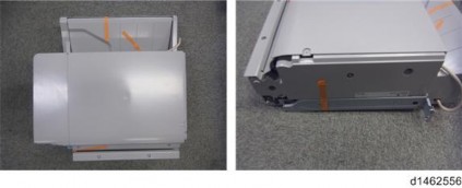
2. Remove the package items (fixing screws, etc.).
3. Open the front cover.
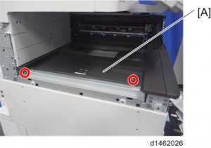
4. Paper output tray [A].
5.
Internal Finisher SR3130
Installation
Installation
Installation
6.
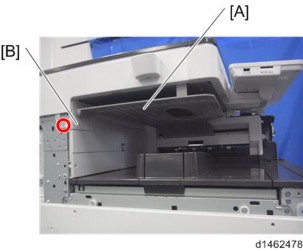
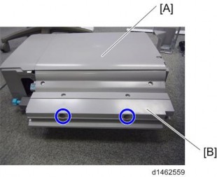
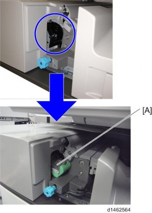
7. Inverter tray [A], tray support plate [B].
8. Open the right cover.
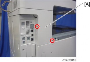
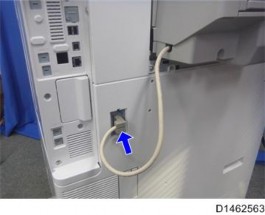
9. Main power switch cover [A] ![]() ×1).
×1).
![]()
Remember that there is a claw at each location in the blue circles.
Internal Finisher SR3130
10.
11. Connector cover [A].
12.
Internal Finisher SR3130
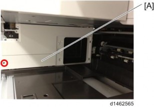
13. Upper rear inner cover [A] ![]() ×1)
×1)
Installation
Installation
Installation
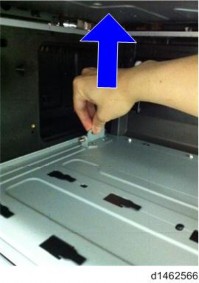
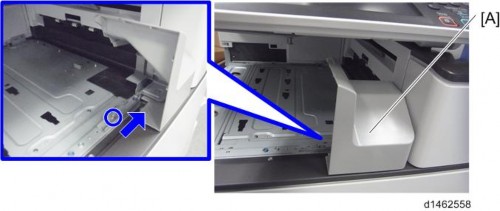
14. While pressing the bottom plate [A] into the area shown by the blue circle [B], insert it into the slot shown by the blue circle [C][D] ![]() ×3).
×3).
The following procedure is the easiest way to set this component.
1) Slip the bottom plate [A] into the position in the blue circle [B].
2) Insert the bottom plate [A] into the hole in the blue circle [C].
3) When the bottom plate [A] is picked up (see below), it can be inserted into the hole in the blue circle [D].
Internal Finisher SR3130
15. Attach the upper rear inner cover.
16. Attach the paper output cover.
![]()
Up to this point, the procedure is the same as punch unit installation (for fitting the punch unit, refer to Step 3 and later of the Punch unit installation procedure).
17. Attach the connector cover.
18. Attach the main power switch cover, and close the duplex unit.
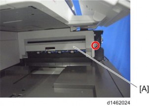
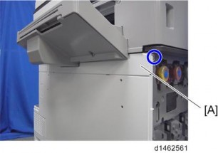
19. Slide the finisher right front cover [A] from left to right to attach it ![]() ×1).
×1).
20. Attach the inverter tray.
21. Attach the relay guide plate [B] to the finisher [A] ![]() ×2).
×2).
Internal Finisher SR3130
Installation
Installation
Installation
22. Slide the finisher [A] along the rail of the bottom plate from the left-hand side of the machine to attach it ![]() ×1).
×1).
23. Attach the left rear cover.
24. Insert the upper left cover [A] from the front, and slide it to attach it.
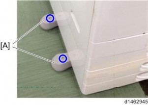
25. Attach stabilizers [A].
![]()
Because the weight is biased to the right of the machine if the inner finisher is installed, anti-tip components are required on the left side. Because they are included with the finisher, install these components at the same time as you install
Internal Finisher SR3130
the inner finisher.
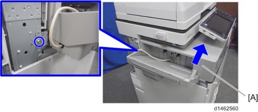
26. Connect the interface cable to the machine.
27. Move forward the stapler unit, then set the stapler [A].
Internal Finisher SR3130
28. Turn the power switch on.
Installation
Installation
Installation
29. Check that the finisher can be selected at the operation panel, and check the finisher operation. Also when punch unit is installed, check the punching operation.