HOME PAGE | < Previous | Contents | Next >
2.16.2 INSTALLATION PROCEDURE
![]()
When installing this option, turn the power source of the machine off, and unplug the power plug from the wall socket.
If it is installed when the power is on, it will result in an electric shock or a malfunction.
Installation
Installation
Installation
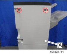
1. Rear upper cover [A] ( ![]() ×2)
×2)
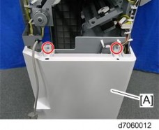
2. Rear lower cover [A] ( ![]() ×2)
×2)
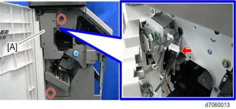
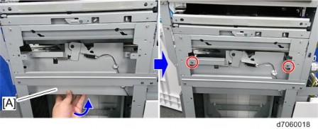
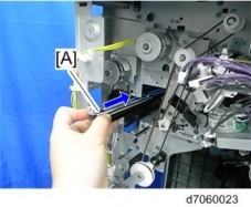
3. Inner cover [A] ( ![]() ×2,
×2, ![]() ×1)
×1)
![]()
There is a connector on the back of the inner cover.
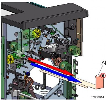
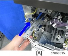
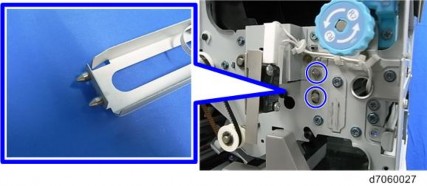
4. Punch guide plate [A]( ![]() ×1)
×1)
Punch Unit PU3060
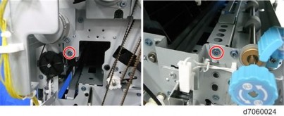
5. Attach the punch unit stay [A]. ( ![]() ×4)
×4)
Rear Front
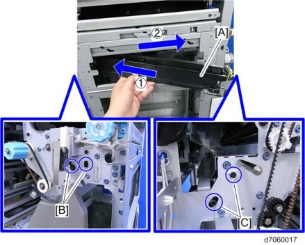
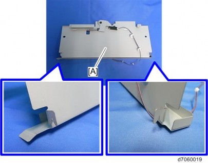
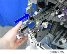
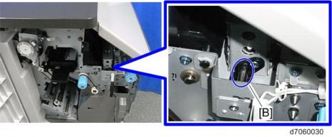
6. Attach the punch waste paper guide [A]. ( ![]() ×1)
×1)
![]()
After inserting the front tab of the punch waste paper guide into the frame [B] of the finisher, insert the rear tab into the frame [C].
Punch Unit PU3060
Installation
Installation
Installation
7. Attach the hopper bracket [A], inserting from the outside frame of the finisher. ![]() ×2, 2 hooks)
×2, 2 hooks)
![]()
Hook the hooks of the hopper bracket onto the back side of the frame.
Punch Unit PU3060
Hook the upper frame of the hopper bracket onto the outside frame of the finisher.
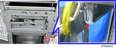
8. Fix the harness of the hopper sensor. ( ![]() ×1)
×1)
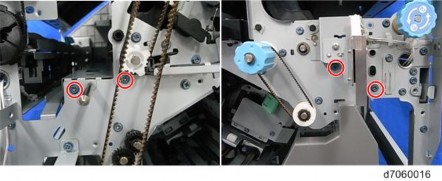
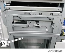
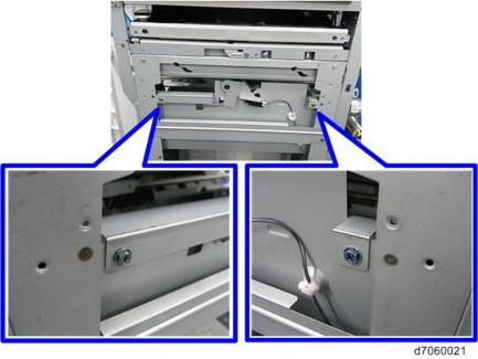
9. Attach the registration guide plate [A]. ( ![]() ×2)
×2)
Punch Unit PU3060
Installation
Installation
Installation
Rear Front
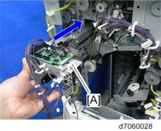
10. Attach the registration mobile unit [A]. ( ![]() ×2)
×2)
![]()
Punch Unit PU3060
Insert the front pins of the registration mobile unit into the holes of the frame.
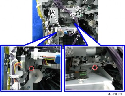
11. Attach the punch unit [A]. ( ![]() ×2)
×2)
![]()
After inserting the pins [B] of the punch unit stay into the front and rear holes of the punch unit, fix the punch unit with two screws.
Rear
Front
Punch Unit PU3060
Installation
Installation
Installation
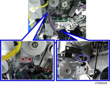
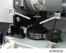
12. Attach the punch stepping motor unit [A]. ( ![]() ×2)
×2)
![]()
Engage the gear [B] of the punch stepping motor unit with the rack [C] of the punch unit.
13. Connect the harness of the hopper sensor to the connector of the finisher.
Punch Unit PU3060
14. Connect the harness of the punch unit to the connector of the registration drive unit.
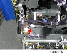
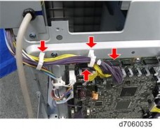
15. Connect the harness of the punch unit to the connector of the main board, and then fix it. ( ![]() ×2,
×2, ![]() ×2)
×2)
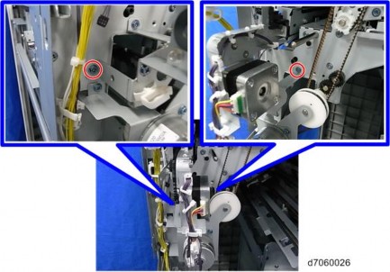
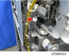
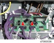
16. Connect the harness [B] of the punch stepping motor unit and the harness [C] of the registration mobile unit to the connector of the punch unit board [A].
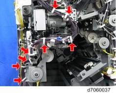
17. Fix all the harnesses of the punch unit PU3060. ( ![]() ×8)
×8)
Punch Unit PU3060
Installation
Installation
Installation
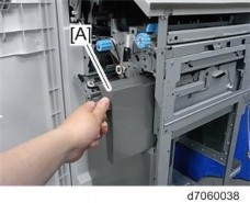
18. Attach the hopper [A].
19. Attach the rear upper cover, the rear lower cover, the inner cover, and the punch guide plate.