HOME PAGE | < Previous | Contents | Next >
2.12 1 BIN TRAY BN3110
Installation
Installation
Installation
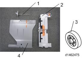
2.12.1 ACCESSORY CHECK
No. | Description | Q’ty |
1 | Tray support bar | 1 |
2 | 1 Bin tray unit | 1 |
3 | gear | 1 |
4 | Tray | 1 |
2.12.2 INSTALLATION PROCEDURE
![]()
When installing this option, turn the machine power off, and unplug the power plug from the wall socket.
If it is installed with the power on, it will result in an electric shock or a malfunction.
1. Remove the orange tape and shipping retainers.
2. Remove the enclosed items (fixing screws, etc.).
3. Open the right cover.
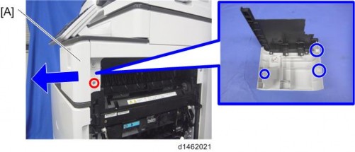
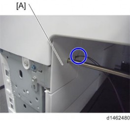
4. Main power switch cover [A] ![]() ×1).
×1).
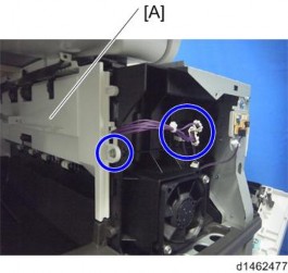
![]()
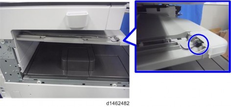
Remember that there is a tab at the positions in the blue circles.
1 Bin Tray BN3110
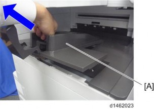
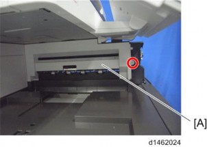
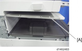
5. Paper output tray [A].
6. Open the front cover.
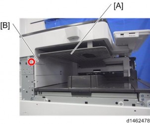
7. Upper left cover [A] ![]() ×1).
×1).
8.
1 Bin Tray BN3110
Installation
Installation
Installation
9.
10. Paper output cover [A] ![]() ×1).
×1).
11. Attach the gear [A] provided.
1 Bin Tray BN3110
12.
![]()
Take care that the harness is not trapped between the 1 bin tray unit and the machine frame.
13. Attach the harness provided.
14.
1 Bin Tray BN3110
![]()
Installation
Installation
Installation
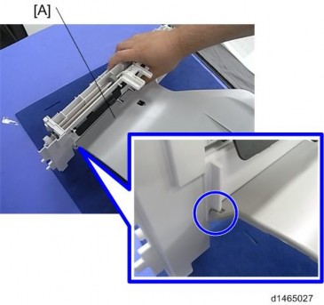
Take out the harness attached in the previous step from the position in the blue circle.
15. Hook the 1 bin tray [A] to the 1 bin tray unit, aligning the positions in the blue circles.
16. Connect the harness to the 1 bin tray, and bring it around.
1 Bin Tray BN3110
17. Insert the tray support bar firmly in the 1 bin tray, and attach the cover [A].
18. Attach the left rear cover, upper left cover and main power switch cover, and close the duplex unit.
19. Turn the power switch ON.
20. Check that output to this tray can be selected on the operation panel, and check operation.