HOME PAGE | < Previous | Contents | Next >
2.11 BRIDGE UNIT BU3070
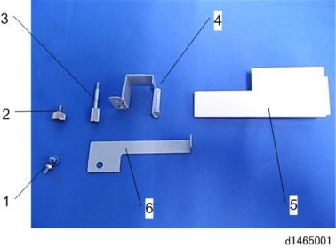
2.11.1 ACCESSORY CHECK
No. | Description | Q’ty |
1 | Tapping screw- M3 × 8 | 1 |
2 | Screw - M4 | 1 |
3 | Knob Screw - M4 | 1 |
4 | Right Front Bracket | 1 |
5 | Left Lower Cover | 1 |
6 | Left Front Bracket | 1 |
2.11.2 INSTALLATION PROCEDURE
![]()
When installing this option, turn the power of the machine off, and unplug the power plug from the wall socket.
If it is installed when the power is on, it will result in an electric shock or a malfunction.
![]()
The bridge unit cannot be used together with the ”Internal Shift Tray SH3070” or “Side Tray Type M3”.
To use together with the “1 Bin Tray BN3110”, attach the “1 Bin Tray BN3110” first before
Bridge Unit BU3070
installing the bridge unit.
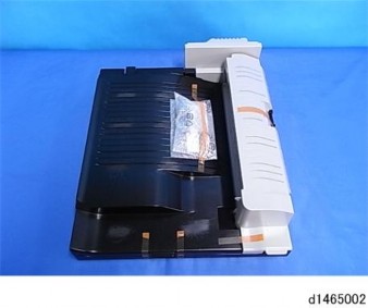
1. Remove the orange tape and shipping retainers.
Installation
Installation
Installation
2. Remove the enclosed items (fixing screws, etc.).
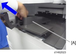
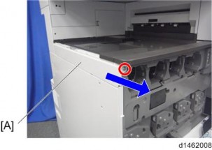
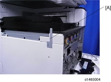
3. Paper output tray [A].
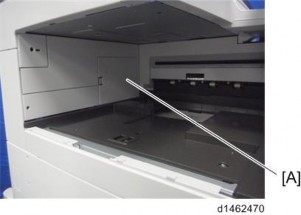
4. Connector cover [A].
5. Open the front cover.
6. Upper left cover ![]() ×1).
×1).
![]()
The screw removed is used again in step 13.
Bridge Unit BU3070
7. Open the right cover.
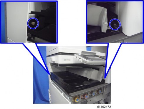
8. Main power switch cover [A] ![]() ×1).
×1).
![]()
Remember that there is a tab at the positions in the blue circles.
9.
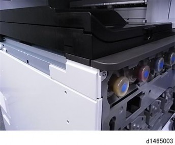
10. Attach the main power switch cover, and close the duplex unit.
11. Attach the bridge unit to the machine ![]() ×2, left rear is a knob screw [A]).
×2, left rear is a knob screw [A]).
Bridge Unit BU3070
Installation
Installation
Installation
12. Close the bridge unit right cover.
13. Attach the upper left cover provided.
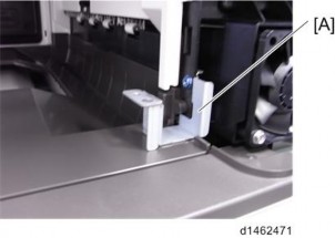
14. Referring to the finisher's installation procedure, attach the L type connecting bracket [A].
Bridge Unit BU3070
15. After the finisher is installed, turn the power switch ON.
16. Check that the finisher can be selected at the operation panel.