Replacement and Adjustment

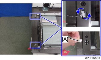
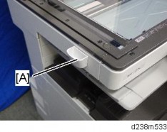
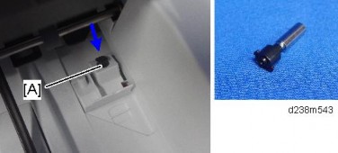
When changing the FFC, stick the Mylar [A] to the new FFC.
When attaching the Mylar, follow the steps below.


When applying the Mylar, be sure not to stretch the FFC.
Applying the Mylar while stretching the FFC causes the circuit board to be deformed.
Replacement and Adjustment

Turn off the main power switch and unplug the machine before beginning any of the procedures in this section. Laser beams can cause serious eye injury.
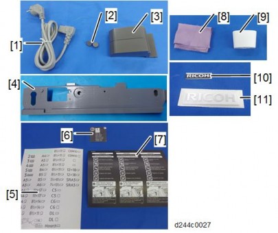
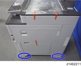
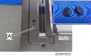
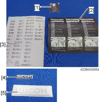
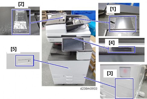
Caution Decals

Decal Location

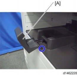
A polygon mirror motor protection bracket and a red tag are attached to each new laser unit. Remove these before you install the new unit.

Replacement and Adjustment


Replacement and Adjustment
Attach the left cover before turning on the main power switch. Laser beams can seriously damage your eyes.
If it is not "0", perform SP2-110-005 again.
If it is not executed correctly, outputs will be abnormal (magnification and color registration errors), and SC 285 may occur.

Check if the margin on either side on the output (14: Trimmed area) is less than 4±1 mm or not. If it is not within these limits, change the reference value (Bk) of the main scanning magnification adjustment (SP2-102-001 to -003).
Adjust the values of the main scanning magnification only for Bk (black). It is not necessary to adjust other color’s values (cyan, magenta, yellow) because other colors are automatically adjusted in relation to the setting for Bk.
Input the same value for each SP (SP2-102-001 to -003) even though there are three SPs of the main scanning magnification adjustment for the standard, middle and low line speed which are used for each paper type.
Check if the margin on the left side on the output (14: Trimmed area) is less than 2±1 mm or not. If it is not within these limits, change the reference value (Bk) of the registration adjustment (SP2-101-001).
SP2-111-004: Forced Line Position Adj. Mode d
The result can be checked with SP2-194-007 (MUSIC Execution Result Execution Result) (0: Success, 1: Failure).
Also, results for each color can be checked with SP2-194-010 to 013 (1: Completed successfully).
Replacement and Adjustment


SP2-111-004: Forced Line Position Adj. Mode d
The result can be checked with SP2-194-007 (MUSIC Execution Result Execution Result) (0: Success, 1: Failure).
Also, results for each color can be checked with SP2-194-010 to 013.
Execution flag to download adjustment values of laser unit to the main unit’s SP. Must be executed when replacing the laser unit or assembling the main unit.
Displays the current skew correction value for each color.
Selects the test pattern.
Adjusts main scan lower speed scale for BK. Value increase: image stretches.
Value decrease: image shrinks
CMY color scale will fit to standard BK speed after executing MUSIC; BK color will have a different scale in the image without executing MUSIC after this SP.
Adjusts main scan registration for BK.
Value increase: image shifts to the right facing the paper. Value decrease: image shifts to the left facing the paper.
CMY colors are adjusted to the BK color position if MUSIC is done after this SP.
Executes the fine line position adjustment and rough line position adjustment.
Displays the result of MUSIC adjustment. 0: Success, 1: Failure
Displays the result code of MUSIC adjustment for each color.
Replacement and Adjustment
Detection Result | Meaning |
0 | MUSIC not executed |
1 | Correction Succeeded: Sampling is conducted correctly and the correction is completed |
2 | Sampling Failed (When the MUSIC pattern failed to be detected) |
3 | Detection Patterns Lacking (When the number of lines detected is smaller than the fixed number) |
4 | The sampled data is beyond the correction range. (Calculated correction value is just out of range) |
5 | The sampled data is beyond the correction range. |
When installing a complete brand-new PCDU, it is not necessary to set SP3-701: New Development Unit detection


Replacement and Adjustment

[A] | Y |
|
[B] | M |
|
[C] | C |
|
[D] | K |
|


[A] | Y |
| x 1, | x 1 |
[B] | M |
| x 1, | x 1 |
[C] | C |
| x 1, | x 1 |
[D] | K |
| x 1, | x 1 |
![]()
![]()
![]()
![]()
![]()
![]()
![]()
![]()
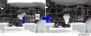
When attaching the PCDU, clamp the harness so that the bind [A] comes above the clamp.

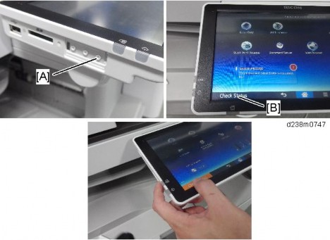
"User Tools" icon > "Machine Features" > "Maintenance" > "Auto Color Calibration" > "Start"
Print the ACC test pattern.
Put the printout on the exposure glass.
Put 10 sheets of white paper on the test chart. This ensures the precise ACC adjustment.
Close the SPDF/ARDF or the platen cover.
Press "Start Scanning" on the LCD. Then, the machine starts the ACC.
Replacement and Adjustment
In the PCU for MP C2504/C2004 and the PCU for MP C6004/C5504/C4504/C3504/C3004, the charging method is different. Variations in the charge voltage must be corrected when a PCU is replaced.
Because of this, before replacing a PCU, do the procedure shown below. The main points are as follows.
Input the charge voltage correction value for the new PCU.
The machine will optimize SP settings related to imaging using process control, after you input the charge voltage correction value and replace the PCU.
Item | SP |
PCU | Black: SP3-701-002 |
Cyan: SP3-701-025 | |
Magenta: SP3-701-048 | |
Yellow: SP3-701- 071 |
0: new unit detection flag OFF, 1: new unit detection flag ON
When installing a complete brand-new PCDU, it is not necessary to input the correction value.
A | Bar code |
B | PCU Lot No. |
C | Correction value |
D | Last three digits of SP number |
E | SP No. |
SP No. (SP name) | |
K | SP2-005-235 (Correction Coefficient c1: K) |
C | SP2-005-236 (Correction Coefficient c1: C) |
M | SP2-005-237 (Correction Coefficient c1: M) |
Y | SP2-005-238 (Correction Coefficient c1: Y) |
If you replace the PCU without inputting the correction value, do the following procedure:
Case 1: When you set SP3-701 to “1”
Input the PCU correction value.
Execute process control manually with SP3-011-001 in order to adjust the machine settings with the PCU correction value.
Case 2: When you did not set SP3-701 to “1” 1. Set SP3-701 to “1”.
Input the PCU correction value.
Turn the power OFF. Note that process control will start automatically.
Replacement and Adjustment
Item | SP |
Development unit | Black: SP3-701-003 |
Cyan: SP3-701-026 | |
Magenta: SP3-701-049 | |
Yellow: SP3-701- 072 |
0: new unit detection flag OFF, 1: new unit detection flag ON
Replacing the development unit resets not only the development unit counter, but also the PCU counter. However, if you change the SP setting (SP3-701) before you replace the development unit, the PM counter of the development unit is reset, but the PM counter of the PCU is not reset.
Therefore, before you replace the development unit, the manual new unit setting
SP3-701 must be done. Doing these in the wrong order will reset the counter of the PCU also.
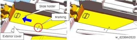
Be careful not to break the plate (shown by the red arrow).

Handle with care to prevent deformation of the plate. Deformation can cause unstable images due to contact failure. Be sure to attach this cover to the PCDU and install the PCDU in the mainframe.

Replacement and Adjustment
When holding the development unit, be sure to obey the following three DO NOTs:

Hold the development unit as shown below:
When separating the PCU and development unit, the drum may come off and this
could cause a toner spillage. Hold the PCU [A] with the drum side up as shown below to prevent toner spillage.
Pay close attention not to spill any toner on the charge roller when assembling.
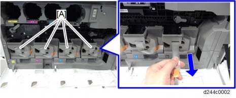
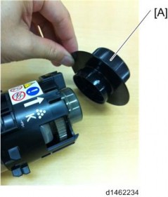
Remove the heat seal [A] after replacing the PCDU.
Remove the cap [B] pasted on the toner port when replacing the PCDU.

Before installing, rotate the drum in the blue arrow direction, to ensure that toner lines do not occur.

Replacement and Adjustment
"User Tools" icon > "Machine Features" > "Maintenance" > "Auto Color Calibration" > "Start"
Print the ACC test pattern.
Put the printout on the exposure glass.
Put 10 sheets of white paper on the test chart. This ensures the precise ACC adjustment.
Close the SPDF/ARDF or the platen cover.
Press "Start Scanning" on the LCD. Then, the machine starts the ACC.


Replacement and Adjustment
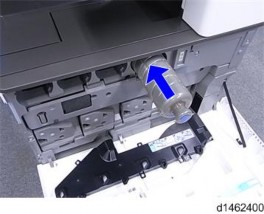
When the bottle is replaced after the machine detects that the waste toner bottle is full and stops, the counter for the Waste Toner Bottle is reset automatically.
When the bottle is replaced before the machine stops due to a full bottle, it is necessary to reset the PM counter manually (set SP3-701-142 to “1” before replacing the bottle, then switch the power off).
This SP is the new unit detection flag.
0: new unit detection flag OFF, 1: new unit detection flag ON
Item | SP |
Waste toner bottle | SP3-701-142 |


Replacement and Adjustment
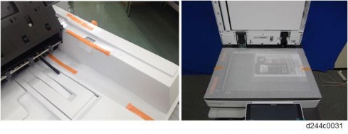
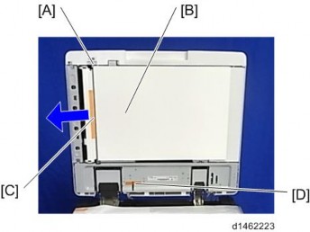
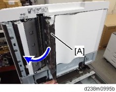
Note that if the two levers [A] [B] are not pointing up, the image transfer belt unit cannot be inserted.
Before you remove or attach the image transfer belt unit, open the right door and the paper transfer unit.
Do not touch the rollers but hold the upper/lower resin parts [A] when you lift the Image Transfer Unit. Touching the rollers may cause poor image quality.
Slowly push the unit until it is inserted all the way, and then give a final strong push one more time. Then lock the ITB lock lever and ITB contact lever.
If the ITB contact lever is locked with the image transfer belt unit not fully inserted into the machine, the paper transfer roller is not set in the correct position when the
paper transfer roller unit is closed. This causes shadows on the image or paper jam, and the paper transfer roller unit may not open.
Before replacing the Image Transfer Belt unit, set SP3-701-093 to "1" and switch the power OFF. Then replace the Image Transfer Belt unit and switch the power ON.
This SP is the new unit detection flag.
0: new unit detection flag OFF, 1: new unit detection flag ON
Item | SP |
Image Transfer Belt Unit | SP3-701-093 |

Replacement and Adjustment


Replacement and Adjustment
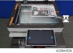
Before removing the image transfer cleaning unit [A], turn the assembly upside down (as shown on the right), so that the image transfer cleaning unit [A] is underneath the image transfer belt unit [B]. This prevents scattering of toner.

When replacing the Image Transfer Cleaning Unit, do not touch the cleaning blade edge.
Before replacing the Image Transfer Belt Cleaning, set SP3-701-102 to "1" and switch the power OFF.
Then replace the Image Transfer Belt Cleaning and switch the power ON.
This SP is the new unit detection flag.
0: new unit detection flag OFF, 1: new unit detection flag ON
Item | SP |
Image Transfer Cleaning Unit | SP3-701-102 |

Replacement and Adjustment


[A]: 20mm or more [B]: About 5mm
It is not necessary to specify the color of the toner, though yellow toner is used in the above example.


Do not touch the rollers but hold the upper/lower resin part [A] when you lift the Image Transfer Unit. Touching the rollers may cause poor image quality.
Replacement and Adjustment

The part in the red circle opens.

Replacement and Adjustment
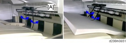
When attaching the belt, make sure that there is no foreign material on it.
Make sure to attach the belt with the edge with markings (2 white dots) at the unit’s rear.
Be careful not to bend or scratch the belt.
Make sure to have the belt’s edge with markings (2 white dots) positioned at the top (unit’s rear).
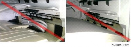
The belt must be attached between the flanges [A] at both ends of the tension roller.
The belt’s edge must be between the two lines [B] on the frame.


Replacement and Adjustment
The part in the red circle closes.


[A]: 20mm or more [B]: About 5mm
It is not necessary to specify the color of the toner, though yellow toner is used in the example above.


Replacement and Adjustment

After replacing the image transfer belt, to prevent twisting of the belt, pass the belt round once in the direction of the arrow.

Replacement and Adjustment
When reinstalling the paper transfer roller, do not install the wrong type of roller.

[A]: Standard roller
[B]: Imageable Area Extension Unit Type M19
When attaching the paper transfer roller, make sure that the roller is set in the correct position while referring to the three points described below.
If the paper transfer roller is set incorrectly, the following problems may occur.
Damage to the image transfer belt
Roller detachment when opening and closing the paper transfer roller unit to remove a paper jam
The paper transfer roller unit does not open
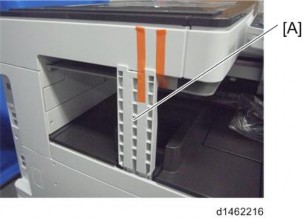
Check that the claw [A] on the roller holder is under the guide plate [B].

Check that the pin [A] on either end of the paper transfer roller is inserted correctly.
Check that the spring [A] at either end of the paper transfer roller unit is in the correct position at each end.
Replacement and Adjustment
Before replacing the Image Paper Transfer Roller Unit, set SP3-701-109 to "1" and switch the power OFF. Then replace the Image Paper Transfer Roller Unit and switch the power ON. SP3-701 (Manual New Unit Set)
This SP is the new unit detection flag.
0: new unit detection flag OFF, 1: new unit detection flag ON
Item | SP |
Paper Transfer Roller Unit | SP3-701-109 |
Note that the sizes of the clip ring differ on the left and right.
When attaching a paper transfer roller unit, first attach the bushings [A] to the paper transfer roller unit.
Replacement and Adjustment
Each sensor assembly has a list of characteristic values attached to it. Before you replace the TM/ID sensor, you must do the following procedure, or process control/MUSIC will not be done correctly after power is switched on (it will use the values for the old sensor).
The characteristic values attached to the service part must be entered before replacement. It is recommended that in case Process control/MUSIC after replacement is not completed successfully, take a note of values of SP3-333, SP3-334 and SP3-335.
TM/ID Sensor (front): F, TM/ID Sensor (center): C, TM/ID Sensor (rear): R, be careful.
Input data for TM/ID Sensor: F into SP3-333. Input data for TM/ID sensor: C into SP3-334. Input data for TM/ID sensor: R into SP3-335.
SP No. | Classification 1 | Classification 2 | Value |
3-333-001 | ID.Sens TestVal:F | K2: Check | TM/ID sensor: F, value of [1] |
3-333-002 | ID.Sens TestVal:F | Diffuse Corr | TM/ID sensor: F, value of [2] |
3-333-003 | ID.Sens TestVal:F | Vct_reg Check:Slope | TM/ID sensor: F, value of [3] |
3-333-004 | ID.Sens TestVal:F | Vct_reg Check:Xint | TM/ID sensor: F, value of [4] |
3-333-005 | ID.Sens TestVal:F | Vct_dif Check:Slope | TM/ID sensor: F, value of [5] |
3-333-006 | ID.Sens TestVal:F | Vct_dif Check:Xint | TM/ID sensor: F, value of [6] |
3-334-001 | ID.Sens TestVal:C | K2: Check | TM/ID sensor: C, value of [1] |
3-334-002 | ID.Sens TestVal:C | Diffuse Corr | TM/ID sensor: C, value of [2] |
SP No. | Classification 1 | Classification 2 | Value |
3-334-003 | ID.Sens TestVal:C | Vct_reg Check:Slope | TM/ID sensor: C, value of [3] |
3-334-004 | ID.Sens TestVal:C | Vct_reg Check:Xint | TM/ID sensor: C, value of [4] |
3-334-005 | ID.Sens TestVal:C | Vct_dif Check:Slope | TM/ID sensor: C, value of [5] |
3-334-006 | ID.Sens TestVal:C | Vct_dif Check:Xint | TM/ID sensor: C, value of [6] |
3-335-001 | ID.Sens TestVal:R | K2: Check | TM/ID sensor: R, value of [1] |
3-335-002 | ID.Sens TestVal:R | Diffuse Corr | TM/ID sensor: R, value of [2] |
3-335-003 | ID.Sens TestVal:R | Vct_reg Check:Slope | TM/ID sensor: R, value of [3] |
3-335-004 | ID.Sens TestVal:R | Vct_reg Check:Xint | TM/ID sensor: R, value of [4] |
3-335-005 | ID.Sens TestVal:R | Vct_dif Check:Slope | TM/ID sensor: R, value of [5] |
3-335-006 | ID.Sens TestVal:R | Vct_dif Check:Xint | TM/ID sensor: R, value of [6] |
Replacement and Adjustment
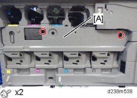
When installing the TM/ID sensor unit.
1. Attach the screw of the front side [B]
2. Attach the screw of the back side [C]
When installed in reverse order, an SC may occur because the sensor position has shifted.
Replacement and Adjustment
If the SP3-011-004 can't finish successfully, make sure you are entering the correct value into the SP.
SP3-011-004 (Manual ProCon :Exe: Full MUSIC) Executes Process Control and full MUSIC.
SP3-012-001 to 010 (ProCon OK?: Front)
Displays the past 10 Process Control result codes detected by the front TM/ID sensor. The code is 2 digits per color from the left, in the order of YMCK.
SP3-012-011 to 020 (ProCon OK?: Center)
Displays the past 10 Process Control result codes detected by the center TM/ID sensor. The code is 2 digits per color from the left, in the order of YMCK.
SP3-012-021 to 030 (ProCon OK?: Rear)
Displays the past 10 Process Control result codes detected by the rear TM/ID sensor. The code is 2 digits per color from left, in the order of YMCK.
Category | Code | Result name | Description |
00 and larger | 00 | Not executed | Factory default setting (SP default) |
10 and larger Result (Normal) | 11 | Succeeded | - |
40 and larger ID Sensor | 41 | ID sensor output error (Max) | Vt > Max |
42 | ID sensor output error (Min) | Vt < Min | |
43 | ID Sensor error (Max) | Development gamma is in target, but Vt value is less than upper limit. | |
44 | ID Sensor error (Min) | Development gamma is in target, but Vt value is less than lower limit. |
Category | Code | Result name | Description |
45 and larger ID Pattern detection | 45 | ID Pattern extract error | Cannot detect ID Pattern |
50 | Vmin_Bk/K2 error (Max) | K:Vmin_Bk / CMY:K2 > Max | |
51 | Vmin_Bk/K2 error (Min) | K:Vmin_Bk / CMY:K2 < Min | |
52 | K5 error (Max) | K5 > Max | |
53 | K5 error (Min) | K5 < Min | |
54 | K5 calculated approximate point error | K5 calculated approximate point < Min | |
55 | Development gamma error (Max) | Development gamma > Max | |
56 | Development gamma error (Min) | Development gamma < Min | |
57 | Start developing voltage: Vk error(Max) | Start developing voltage: Vk > Max | |
58 | Start developing voltage: Vk error(Min) | Start developing voltage: Vk < Min | |
59 | Not enough valid data | Adhesion amount data for development gamma calculation point is under 2. | |
90 and larger Result(End) | 90 | Potential not adjusted | Potential control method is set as [0:FIX]. |
99 | Stopped | Stopped by door open, power off, error. (Set when execute.) |
Execution result example (In order of YMCK from left)
Factory default (SP default): [00,00,00,00]
Starting adjust: [99,99,99,99]
Fail Vsg adjust(Y): [21,99,99,99]
Error of Development gamma Max(C): [99,99,55,99]
Succeeded: [11,11,11,11]