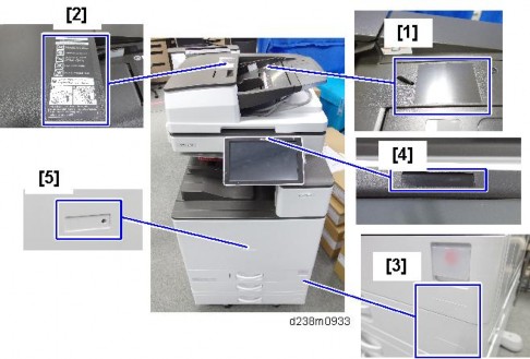
Preventive Maintenance
Clean the exposure glasses (for DF and book scanning).
Enter the user tools mode.
Do the "Automatic Color Calibration (ACC)" for the copier mode & printer mode as follows:
Print the ACC test pattern (User Tools > Maintenance > ACC > Start).
Put the printout on the exposure glass.
Put 10 sheets of white paper on the test chart. This ensures the precise ACC adjustment.
Close the ARDF or the platen cover.
Press "Start Scanning" on the LCD. Then, the machine starts the ACC.
Exit the User Tools mode, and then enter the SP mode.
Perform line adjustment.
SP2-111-004: Forced Line Position Adj. Mode d
The result can be checked with SP2-194-007 (MUSIC Execution Result Execution Result) (0: Success, 1: Failure).
Also, results for each color can be checked with SP2-194-010 to 013.
Exit the SP mode.
SP Descriptions
SP2-194-007 (MUSIC Execution Result: Execution Result)
Displays the result code of MUSIC adjustment. 0: Success
1: Failure
SP2-194-010 to 013 (MUSIC Execution Result: Error Result C,M, Y, K)
Displays the result code of MUSIC adjustment for each color. 0: Not done
1: Completed successfully 2: Cannot detect patterns
3: Fewer lines on the pattern than the target 4: Out of the adjustment range
5 to 9: Not used
Check if the sample image has been copied normally.
Preventive Maintenance
RE V IS ION H IST ORY | ||
Page | Date | Added/ Updated/ New |
None | ||
Replacement and Adjustment
The main power button of this machine has been changed to a push-button switch (push button) from the conventional rocker switch. The push switch has characteristics and specifications different from the rocker switch. Care must be taken when replacing and adjusting parts.
Characteristics of the Push Switch (DC Switch)
Power is supplied to the machine even when the main power switch is turned OFF.
The push switch in this machine uses DC (direct current). Therefore, if the AC power cord is connected to an electrical outlet, power is supplied to the controller board, the operation unit and other modules even when the main power is turned OFF. When replacing the controller board and the operation unit in this state, not only these boards, it will damage other electrical components.
So, when performing maintenance work such as replacing parts, in addition to turning off the main power with the push switch, always unplug the AC power cord.
When you disconnect the power cord from the AC wall outlet, inside the machine there is still residual charge.
When you disconnect the power cord from the AC wall outlet, inside the machine for a while there is still residual charge. Therefore, if you remove boards in this state, it can cause a blown fuse or memory failure.
How to remove the residual charge inside the machine
After you unplug the power cord from the AC wall outlet, in order to remove the residual charge from inside the machine, be sure to press the main power switch. Thus, the charge remaining in the machine is released, and it is possible to remove boards.
When you reconnect the AC power cord into an AC wall outlet, the machine will start automatically.
In order to remove the residual charge, push the main power switch while you disconnect the AC power cord. At that time, the power ON flag inside the machine is set. Therefore, after you finish work on the machine and reconnect the power cord to the AC, even if you do not press the main power switch, the machine will start automatically and the moving parts will begin to move. When working on moving parts, be careful that fingers or clothes do not get caught.
Automatic restart deals with cases when you accidentally unplugged the AC power cord or unexpected power outages. By keeping the power flag ON, after the resumption of power, the machine will start up automatically.
In rare cases, when you reconnect the AC power cord to a power outlet, the machine does not start automatically. In this case, the machine has not failed. The cause is due to the timing of releasing the residual charge. If you press the main power switch while the residual charge was already released, the power ON flag will not be set. At this time, start the machine manually by pressing the main power switch.
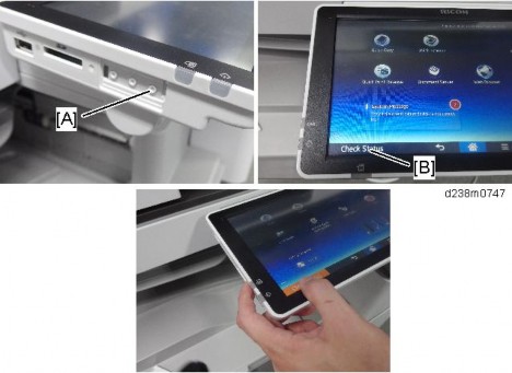
Shutdown Method
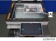
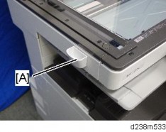
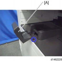
Press the main power switch [A] on the machine.

The shutdown message appears. After the shutdown process, the main power is turned off automatically.
The operation panel and the main power indicator are turned off when the machine completes the shutdown.
Even after the shutdown message disappears, do not disconnect the power cord while the main power indicator [A] is flashing to indicate that the machine is still shutting down.
Before removing and adjusting electrical boards, do the following procedure. Otherwise, the board can be damaged by the residual charge inside the machine and must be replaced.
Replacement and Adjustment
Take out the power cord after shutdown.
Press the power switch for a second to remove the residual charge inside the machine.
Forced Shutdown
In case normal shutdown does not complete for some reason, the machine has a forced shutdown function.
To make a forced shutdown, press and hold the main power switch for 6 seconds. In general, do not use the forced shutdown.
Forced shutdown may damage the hard disk and memory, and can cause damage to the machine. Use a forced shutdown only if it is unavoidable.
Turn off the main power switch and disconnect the power cord.
After replacing, make sure that all harnesses that were removed are connected up again and secured in their clamps.
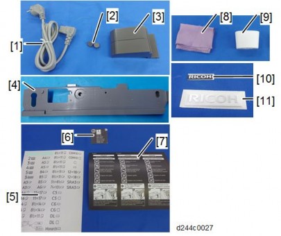
Item | Part Number | Description | Q’ty | Unique or Common |
1 | A1849501 | Scanner Positioning Pin (2pcs/set) | 1 | C (General) |
2 | B6455020 | SD Card (1GB) | 1 | C (General) |
3 | B6455060 | SD Card (16GB) | 1 | C (General) |
4 | 52039502 | Silicone Grease G-501 | 1 | C (General) |
5 | A2579300 | Grease Barrierta – S552R | 1 | C (General) |
6 | C4019503 | 20× Magnification Scope | 1 | C (General) |
7 | VSSG9002 | FLUOTRIBO MG GREASE: 100G | 1 | C (General) |
8 | A0929503 | C4 Color Test Chart (3 pcs/set) | 1 | C (General) |
A PC (Personal Computer) is required for creating the Encryption key file on an SD card when replacing the controller board in which HDD encryption has been enabled.
Replacement and Adjustment
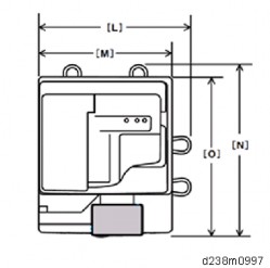
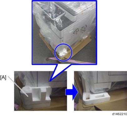
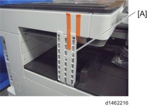
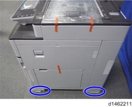
Precaution Concerning Stabilizers
The stabilizers are necessary for meeting the requirements of IEC60950-1, the international standard for safety.
The aim of these stabilizers is to prevent the products, which are heavy, from toppling as a result of people running into or leaning onto the products, which can lead to serious accidents such as persons becoming trapped under the product. (U.S.: UL60950-1, Europe:
EN60950-1)
Therefore, removal of such stabilizers must always be with the consent of the customer. Do not remove them using only your own judgment.
Front and Rear Side Covers

No. | Cover name |
1 | Waste toner cover |
2 | Front upper cover |
3 | Front cover |
4 | Main power switch cover |
5 | Rear cover |
6 | Rear lower cover |
Replacement and Adjustment
Right and Left Side Covers

No. | Cover name |
1 | Right upper cover |
2 | Right door |
3 | Right rear cover |
4 | Left rear cover |
5 | Controller cover |
6 | Left cover |
7 | Upper left cover |
Paper Exit Covers

No. | Cover name |
1 | Paper exit tray |
2 | Inverter tray |
3 | Paper exit cover |
4 | Paper exit lower cover |
Inner Covers

No. | Cover name |
1 | Paper exit front cover |
2 | Inner upper cover |
3 | Inner lower cover |
Replacement and Adjustment
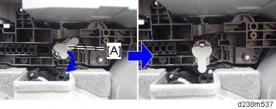
Open the front cover [A].

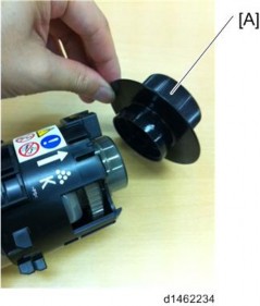
Unhook the belt’s tip and detach the belt [A].

Pressing down the stopper, slide the front cover [A] to the right and detach it.

1. Controller cover [A]


Each part enclosed by a blue circle has a tab. Be careful not to damage it when attaching and detaching.
Open the front cover.
Paper exit tray (page 4-21)
Upper left cover [A]
Slide the cover in the direction of the blue arrow.

Replacement and Adjustment
Upper left cover (page 4-10)
Left Rear Cover [A]

Each part enclosed by a blue circle has a tab. Be careful not to damage it when attaching and detaching.

Controller cover (page 4-10)
Ozone filter/Dust filter box (page 4-207)
Upper left cover (page 4-10)
Left rear cover (page 4-11)
Open the 2nd paper feed tray slightly.

Replacement and Adjustment
Left cover [A]
Remove it while pressing down.

Order to remove

Paper exit tray
Controller cover
Ozone filter/Dust filter box
Front cover
Upper left cover
Left rear cover
2nd paper feed tray
Left cover
There are tabs (left-facing) on the back face of the rear cover. When fitting or removing the cover, take care not to damage it.
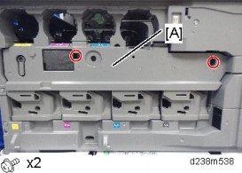
1. Rear cover [A]

Slightly bend the cover to release the tabs behind the parts indicated by red circles and release the cover.

Replacement and Adjustment
Rear cover (page 4-14)
Rear lower cover [A]

Open the right door.
Right rear cover [A] ![]() x4, among them, tapping screw x1)
x4, among them, tapping screw x1)

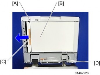
When installing, insert the projections [A] in the holes [B], taking care not to trap the harness inside.

Replacement and Adjustment
Front upper cover (page 4-17)
Right upper cover [A]

Open the right door.
Small cover [A]

Remove the screw and the connector, and then remove the front upper cover [A].

Remember that there are three tabs at the positions in the red arrows.
Tilt the operation panel [B] upward to a horizontal position, and then remove the front upper cover [A].

Front upper cover (page 4-17)
Two connectors

Bracket [A]

Proximity sensor (Human detection sensor) [A]

Replacement and Adjustment
Pull out the paper trays 1 and 2.

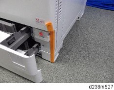
Main power switch cover [A].

Front cover (page 4-9)
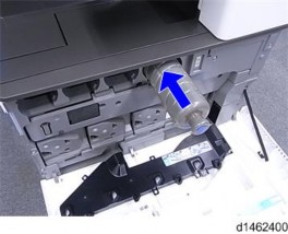
Open the waste toner cover [A].

Waste Toner Cover [A]

1. Inverter Tray [A]

Replacement and Adjustment
1. Paper Exit Tray [A]

Front upper cover (page 4-17)
Paper exit tray (page 4-21)
Inverter Tray (page 4-20)
Paper exit cover [A]

Left rear cover (page 4-11)
Paper exit cover (page 4-21)
Connector cover [A].

Paper exit lower cover [A]

Replacement and Adjustment
Front upper cover (page 4-17)
Paper exit lower cover (page 4-22)
Paper exit front cover [A]

Open the front cover, and remove the belt. (page 4-9)
Open the right door.
Paper exit front cover (page 4-23)
Image transfer belt unit (page 4-71)
Inner upper cover [A]

Front cover (page 4-9)
Inner upper cover (page 4-23)
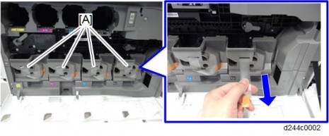
PCDU cover (Y) [A]

Waste toner cover (page 4-20)
Inner lower cover [A]
Replacement and Adjustment
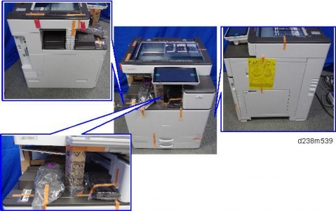
This section explains how to remove the Smart Operation Panel from the machine. For details about disassembling the Smart Operation Panel, See the service manual for Smart Operation Panel 2nd Generation.
Scanner front cover (page 4-33)
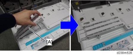
Holding down both the sides of the operation panel upper cover [A], unhook the tabs (indicated by blue circles) and remove the cover.

Operation panel [A]
Open the platen cover or ADF.
Spread a cloth or service mat [A] on the exposure glass to protect the display. Place the operation panel on the exposure glass so that the display faces down.
Rear center cover [A]

Disconnect the USB cable [A].

Left small cover [A], right small cover [B]

Right hinge cover [A] (Hook x 2)

Replacement and Adjustment
Left hinge cover [A], right cover [B]

Hinges [A] [B]
Rear cover (page 4-14)
Scanner right cover (page 4-34)
Controller box cover (page 4-182)
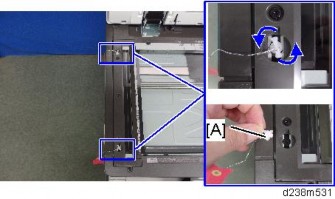
Disconnect the USB cable [A]

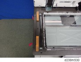
Remove the clamps on the cables under the scanner unit.

When removing a clamp, insert a long flathead screwdriver or such a tool from the side to remove it.
Replacement and Adjustment
The cable has a set of 2 cable ties. When attaching the cable, position the clamp between the two cable ties.
Rear cover (page 4-14)
Cable bracket and connector SPDF DF3100
ARDF DF3090

Replacement and Adjustment
Screws on the ADF base. SPDF DF3100

ARDF DF3090

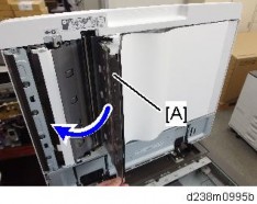
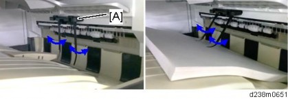
Slowly and carefully (the ADF is heavy) lift the ADF [A] off the machine.
Set the ADF on its edge on the floor, and then lean it against a wall [B].
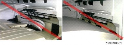
To prevent damage to the fragile feelers [A] of the ADF position sensor, never lay the ADF on a flat surface as shown below.
If the SPDF DF3100 is being replaced, do SP4-730-002 after the new SPDF has been installed.
SP descriptions
SP4-730-002 (FROM Main Factory Setting Execution ON/OFF)
Copies the parameters written in FROM in the SPDF to the engine board in the MFP. This SP is only for the SPDF models.
Replacement and Adjustment
There is no SIO (Scanner Interface Board) in this machine. The functions of the SIO of the previous machine are controlled by the IPU. Harnesses of the scanner unit connect directly to the IPU in the controller box on the back of the machine.

Scanner Front Cover
1. Scanner front cover [A]
Scanner Right Cover
Remove the screw.

Scanner right cover [A]
Remove the hook at the top, and then slide the cover towards the rear.
Replacement and Adjustment
Scanner Left Cover
Scanner front cover (page 4-33)
Scanner left cover [A]
Scanner Upper Cover
Platen cover or ADF
Rear cover (page 4-14)
Scanner Upper Cover [A]

Open the platen cover or ADF.
Scanner right cover (page 4-34)
Scale [A]

Sheet-through exposure glass [A]

Rear scale [A]

Left scale and exposure glass [A]
The exposure glass and the left scale are attached with double-sided tape.
Replacement and Adjustment
When installing, please follow the points below:
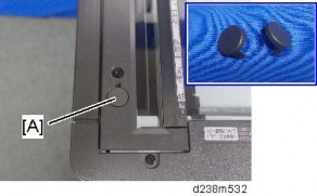
Install the sheet-through exposure glass with the mark [A] at the rear left corner.
Set so that the locating hole of the left scale fits over the locating boss of the front/rear frame.
Exposure glass (page 4-36)
Scanner front cover (page 4-33)
Scanner carriage front cover [A]
Move the scanner carriage [A] to the indicated position as shown.
Loosen the screw, remove the spring [A], and then remove the belt [B].

Turn the scanner carriage over and place it on the frame [A].

When holding the scanner carriage, be careful not to touch the circuit board [A], lens [B], and mirror [C].
Replacement and Adjustment
Belt [A]
Lower the lock lever [A] and disconnect the FFC [B].
Ferrite core [A], Mylar sheet [B] (Hook x 4)

Scanner carriage

When attaching the scanner carriage, hold the carriage with the screw [A] loosened and move the carriage back and forth to the sides twice to have the belt stretch evenly. Then, fasten the screw [A].
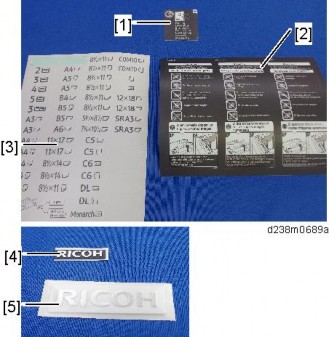
After replacing the scanner carriage, enter the values supplied with the carriage in the following SP
SP4-871-002 (Distortion Correction Distortion Initialization)
SP4-880-001 (Dot shift amount between R Line and G Line).
SP4-880-002 (Dot shift amount between G Line and B Line).
To apply the specified settings, turn the power off and then back on.
The specified values are cleared when the NVRAM is initialized, so be sure to keep the supplied sheet showing the values in the machine.
Replacement and Adjustment
Cleaning the Scanner Carriage Mirror
Exposure glass (page 4-36)
Scanner carriage front cover [A]

Move the scanner carriage [A] to the indicated position as shown.

Resin cover [A] (Hook x 3)
Open the metal cover [A]
Wipe clean the mirror with a dry cloth.

When reattaching the metal cover [A], fasten the screws in the order of "1", "2", and "3".
When attaching the resin cover, insert its tip under the metal frame.

Replacement and Adjustment
Scanner upper cover (page 4-35)
Rear cover (page 4-14)
Grounding plate [A]

Spring [A]
Scanner motor with bracket [A]

Bracket [A]

Exposure glass (page 4-36)
APS sensor harness cover [A]

APS sensors [A] (Hook x 4)
Replacement and Adjustment
Exposure glass (page 4-36)
Slide the scanner carriage [A] in the direction of the arrow.
Scanner HP Sensor [A] (Hook x 3)
Scanner upper cover (page 4-35)
ARDF/Platen cover sensor [A]
Exposure glass (page 4-36)
Remove the FFC from the scanner carriage (page 4-37)
Original size sensor harness cover [A]
Remove the double-sided tape.
When reattaching the same part, apply a double-sided tape again.